TR7500_Series_Software_v29_En - 第34页
Test Research Inc. 12 TR7500 Series User Guide – Software v.2.9.0 Figure 18: Set First Compo nent in Board 1 (2) Input the objectiv e component name. Figure 19: Sel ect a Compon ent Name (3) Locate the speci f ied compon…
Test Research Inc.
TR7500 Series User Guide –Software v.2.9.0 11
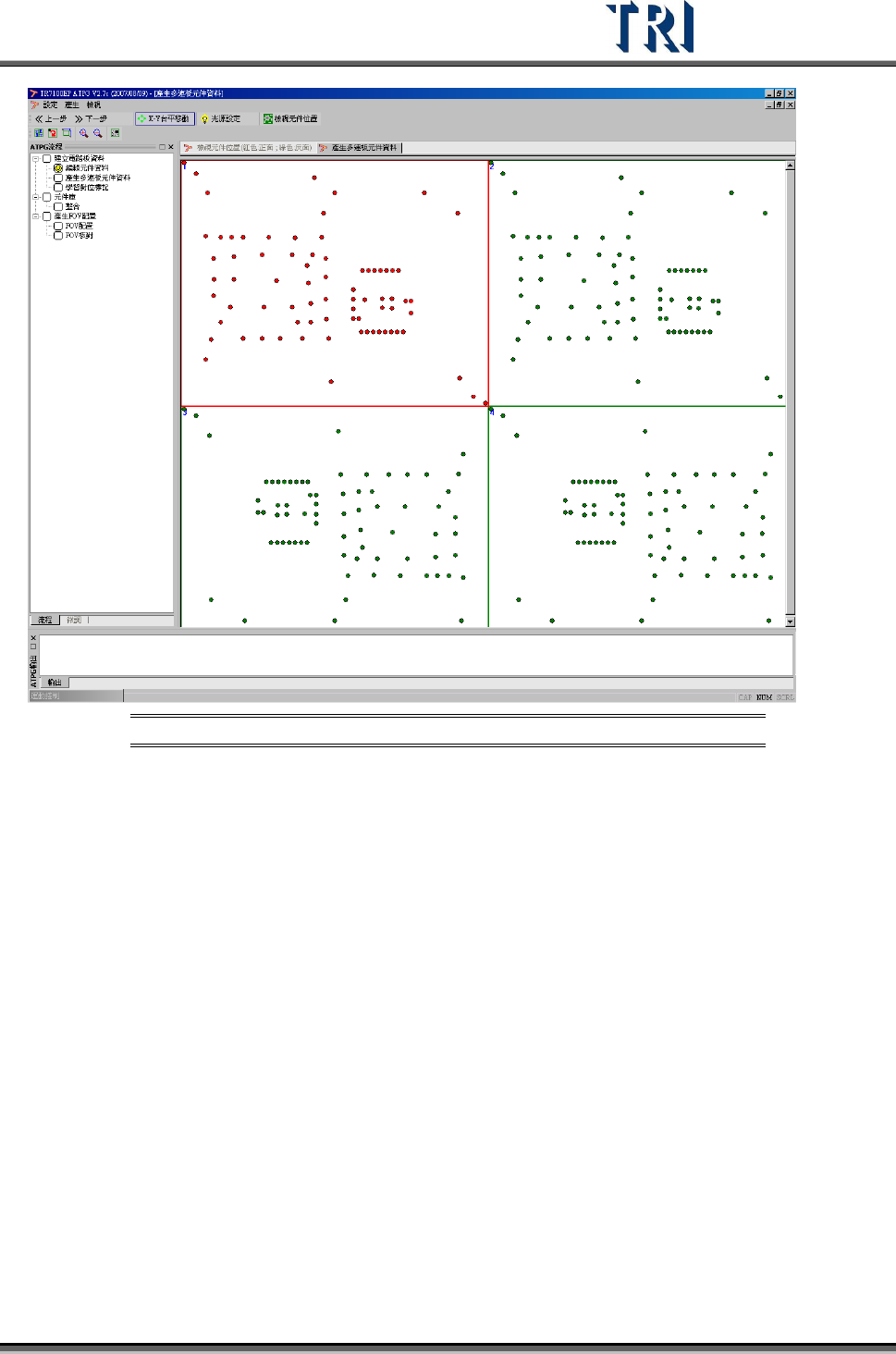
Figure 17: Set Board 1 with CAD Relationship
2.5.2 Get Board Rotation Angle (Find R1, R2)
When it is a multi-board panel, user has to find a component in Board 1 and locate it, and
system will specify the same component in the other board for user to locate.
When it is a single board panel or a panel with different sides, the board angle can be
determined from two components on the board. It is better for board angle detection that the
two components have maximum distance from each other.
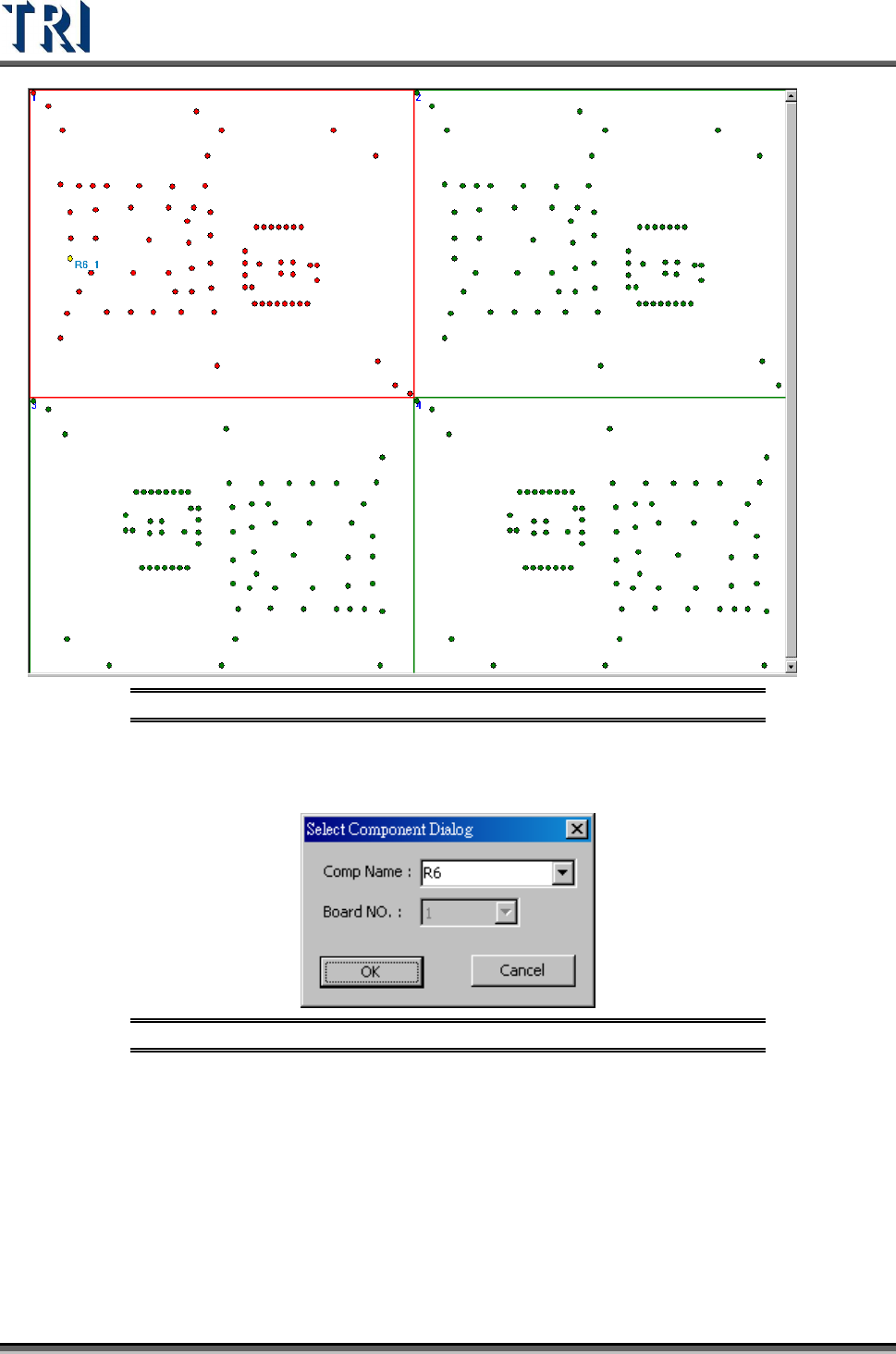
(1) Double click on the objective component in Board 1.
Test Research Inc.
12 TR7500 Series User Guide –Software v.2.9.0
Figure 18: Set First Component in Board 1
(2) Input the objective component name.
Figure 19: Select a Component Name
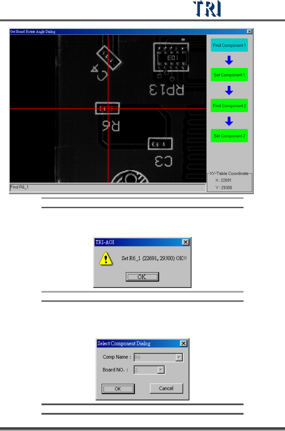
(3) Locate the specified component. Move camera to center of the component. Use
[Motion Control] function to move camera to specific direction and distance or click right
button of mouse on image zone to move the camera to the mouse position. Adjust the
size of red frame to suit the specific component. The center can easily be found.
Test Research Inc.
TR7500 Series User Guide –Software v.2.9.0 13
Figure 20: Use Camera to Set the First Component
(4) Press [Set Component 1] to get the position of first component.
Figure 21: Confirm CAD Coordinates
(5) System will specify the corresponding second component (R2). If system doesn’t
specify, user has to find the second component on Board 1.
Figure 22: Select Second Component