TR7500_Series_Software_v29_En - 第74页
Test Research Inc. 52 TR7500 Series User Guide – Software v.2.9.0 Figure 94: Multi-B arcode L ayout Dialog
Test Research Inc.
TR7500 Series User Guide –Software v.2.9.0 51
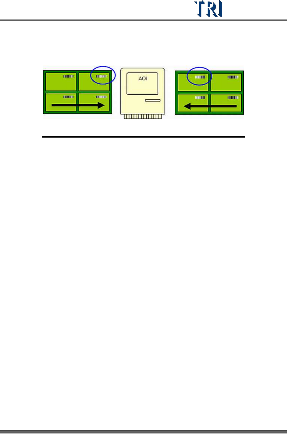
left, read the barcode on the board that is at the upper right corner. If the PCB is
sent to the machine from the right side, read the barcode on the board that is at the
upper left corner. When this item is checked, remember to set the arrangement in
[Multi Barcode Layout].
Figure 93: Panel Input Direction from Left or Right
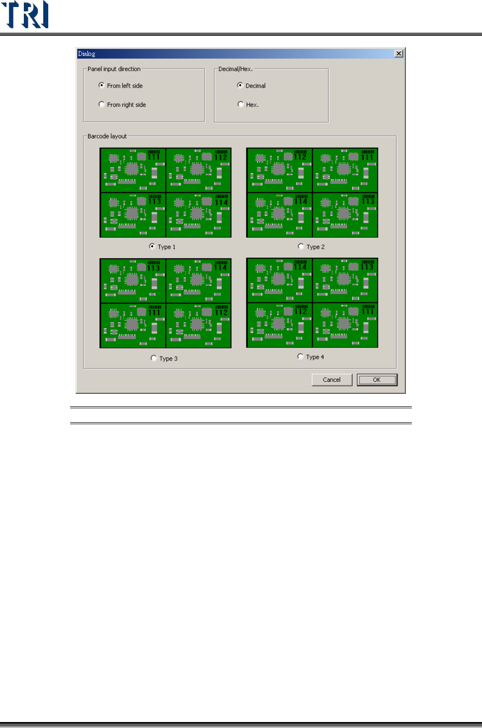
[Multi Barcode Layout] – Only when the value in [Barcode count in one panel] is
greater than 1, this button becomes active and allows users to enter the [Barcode
Layout Dialog] as shown in the following figure.
[Panel input direction] – Set the input direction [From left side] or [From right side]
[Decimal/Hex]. – Set the barcode type.
[Barcode layout] – Set the corresponding layout of the multi-board.
Test Research Inc.
52 TR7500 Series User Guide –Software v.2.9.0
Figure 94: Multi-Barcode Layout Dialog
Test Research Inc.
TR7500 Series User Guide –Software v.2.9.0 53
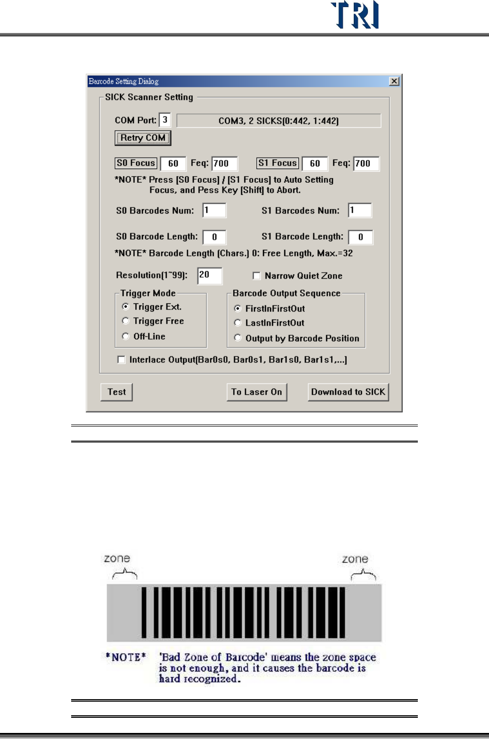
3.3.4.2 Barcode Setting Dialog
Figure 95: Barcode Setting Dialog
Step1. Make sure the Barcode is detected in COM3. If it displays [COM3, 1 SICK] as
in the above figure, it is normal. If it does not display [COM3, 1 SICK], click
[Retry Com] to search again. If you still cannot find it, you need to check the
hardware and see if it is in good order.
Step2. If the “quiet zone” is too narrow (as shown in the following figure), the barcode
will be difficult to be identified. Select [Narrow Quiet Zone].
Figure 96: Barcode “Quiet Zone”