TR7500_Series_Software_v29_En - 第83页
Test Research Inc. TR7500 Series User Guide – Software v.2.9.0 61 [Send to Repai r] – W hen t his item is selec ted, t he serial nu m ber is sent to R epair Station and located on [BarcodeSN ] field. 3.4 Prog ram Tab F…
Test Research Inc.
60 TR7500 Series User Guide –Software v.2.9.0
[Path] – Set repair data saving path for repair station. Default setting is
[\\RepairPC\C\AOI_Repair_Data].
[Change Type to Part Number] – Choose this option to send [Type] data to repair
station in the [Hidden Type] field.
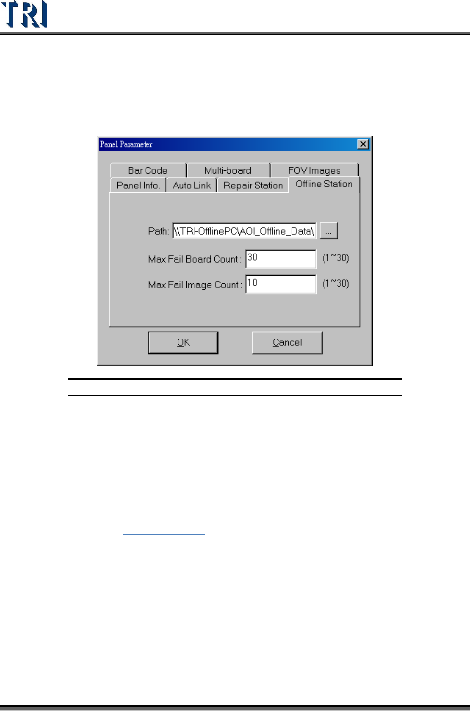
3.3.10 Offline Editor
Figure 107: Panel Parameter – Offline Editor Tab
[Path] – Set offline data save path for offline editor. Default is
[\\OfflinePC\C\AOI_Offline_Data].
[Max Fail Board Count] – This is the maximum inspecting number that the Offline
Editor can save. This means that the Offline Editor saves the latest 30 data only
when 30 is set in this field.
[Max Fail Image Count] – This is the maximum number of failed images that AOI
will transfer to Offline Editor. It means that AOI only transfers the previous 10 failed
images to Offline for every inspection when ‘10’ is set in this field.
See Chapter
15 Offline Editor for more information about Offline Editor.
3.3.11 Software Barcode
This is an optional function. After [Software Barcode] is enabled, the barcode can be read by
the system camera.
3.3.12 Assign Serial Code
The function is usually used where there is no barcode on the PCB. Assign the serial number
for the PCB. The serial number can show in the results dialog or translate to Repair Station.
Input the initial number first then press [OK] to start this function.
Test Research Inc.
TR7500 Series User Guide –Software v.2.9.0 61
[Send to Repair] – When this item is selected, the serial number is sent to Repair
Station and located on [BarcodeSN] field.
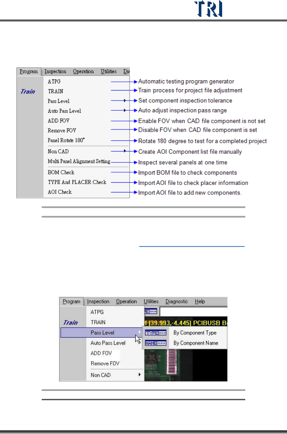
3.4 Program Tab
Figure 108: Program Tab
3.4.1 ATPG
Press to enter the [ATPG] flow. See Chapter 4 AOI ATPG Function Instruction.
3.4.2 TRAIN
Press to enter the [Train] dialog.
3.4.3 Pass Level
Figure 109: Program – Pass Level
Test Research Inc.
62 TR7500 Series User Guide –Software v.2.9.0
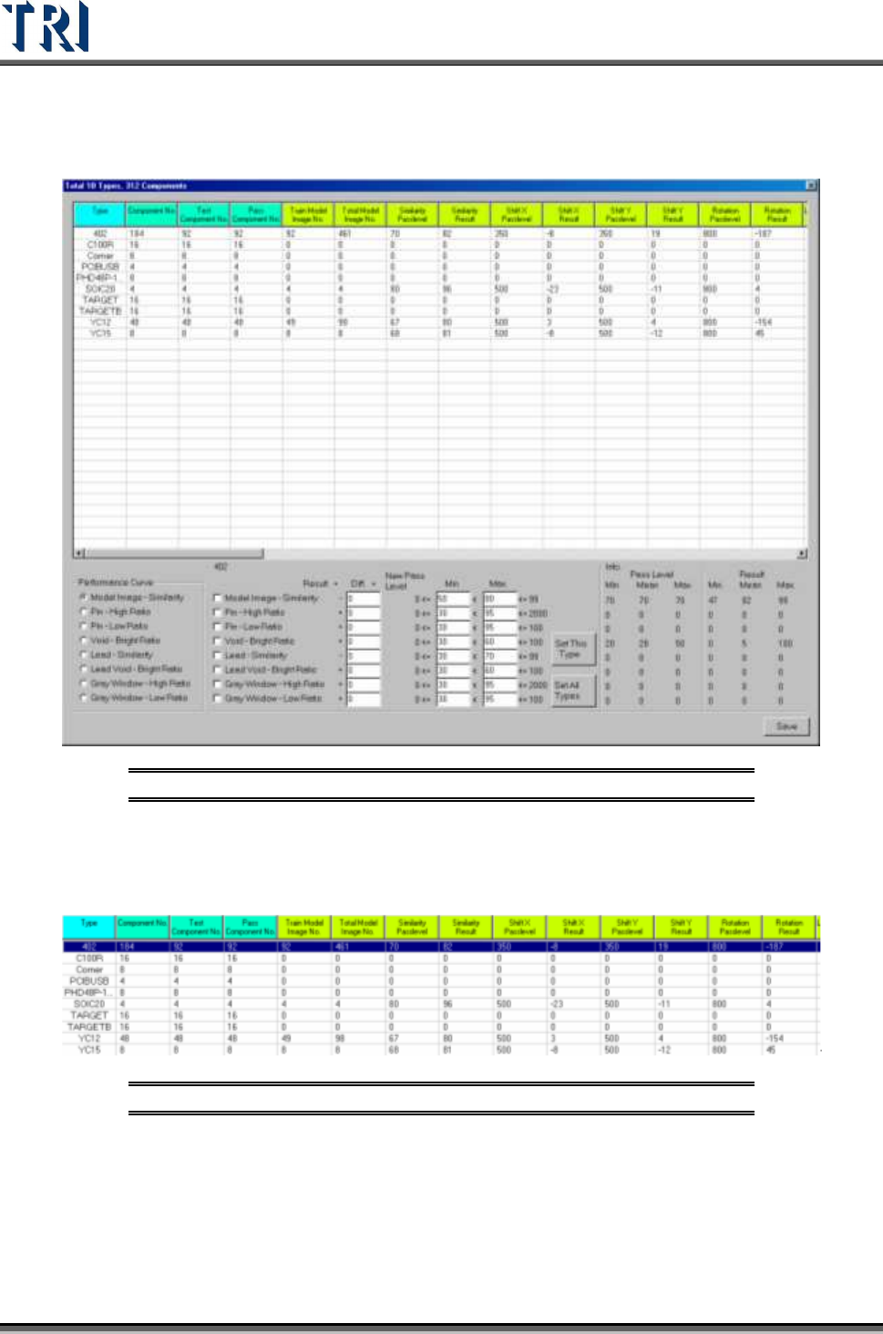
3.4.3.1 By Component Type
Set the pass level by component type. After selection the following window appears.
Figure 110: Sample Component List
In the table the first four columns display the component information and the following
columns show the information of different inspection boxes. Double click on the inspection
result cell to edit the pass level.
Figure 111: Four Fields to Edit in Component List
Select a kind of inspection box in [performance curve] and double click on the type name in
table then it will show the result of all components in this type. The horizontal axis is for every
component and the vertical axis means the score. The green points mean the average result
of every component and the red points mean the pass level of every component. Click to
show the component name and score.