TR7500_Series_Software_v29_En - 第94页
Test Research Inc. 72 TR7500 Series User Guide – Software v.2.9.0 (3) [Tools] - Use these f our tools, plus the La rge Component T ool, to create a CA D file. ICON NAME DESCRIPTION Box The Box tool defines the coordinate…
Test Research Inc.
TR7500 Series User Guide –Software v.2.9.0 71
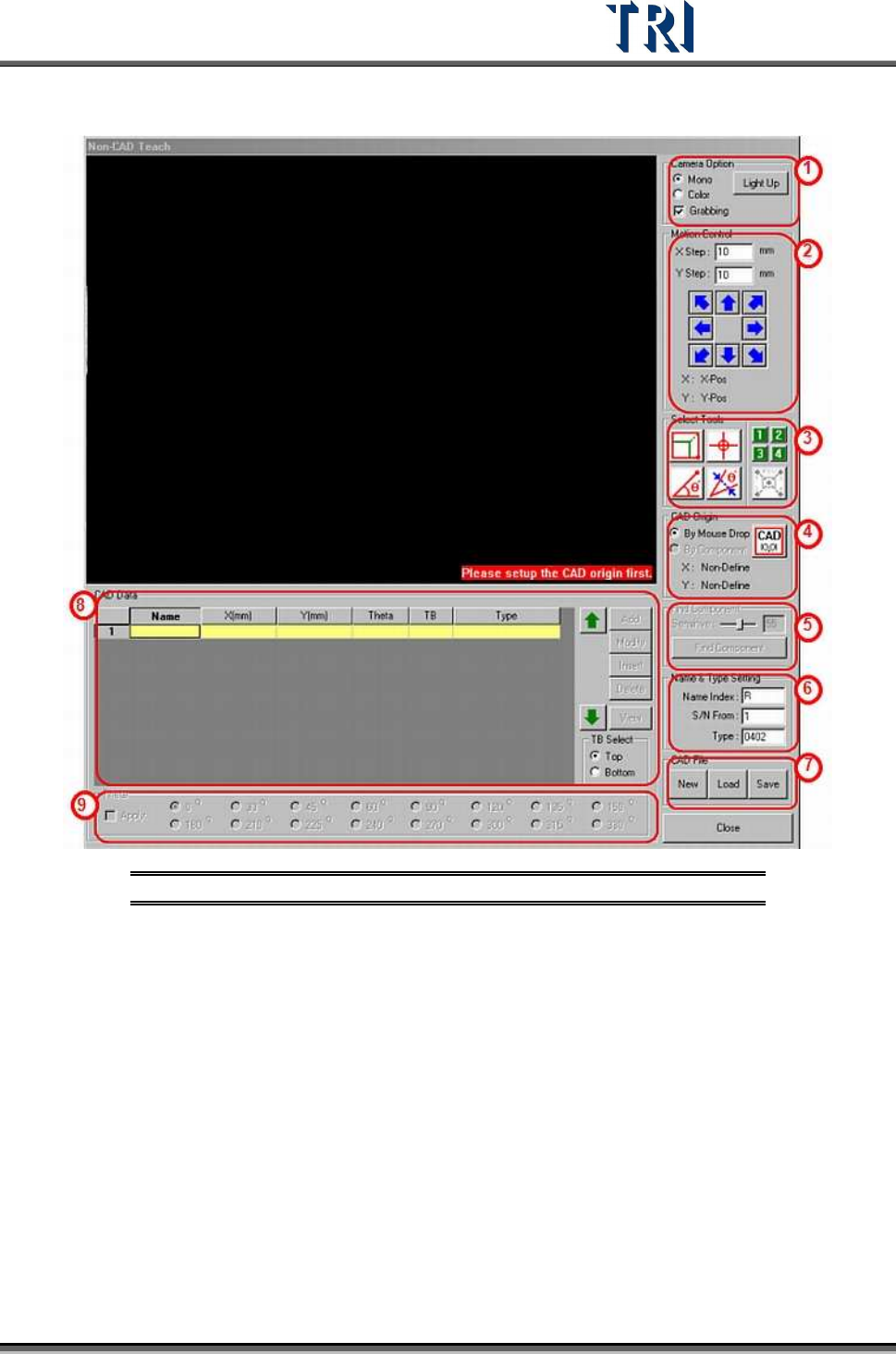
3.4.8.2 Non-CAD Teach Interface Introduction
Figure 124: Non-CAD Teach Window & Functions
(1) [Camera Option] - Check [Grabbing] to capture real time image. You can select [Mono]
to see gray image or [Color] to see color image. Press [Light Up] to set the lighting.
(2) [Motion Control] - You can use the function to move camera to specific direction and
distance or right click mouse on the image area to move the camera to specific position.
Test Research Inc.
72 TR7500 Series User Guide –Software v.2.9.0
(3) [Tools] - Use these four tools, plus the Large Component Tool, to create a CAD file.
ICON
NAME DESCRIPTION
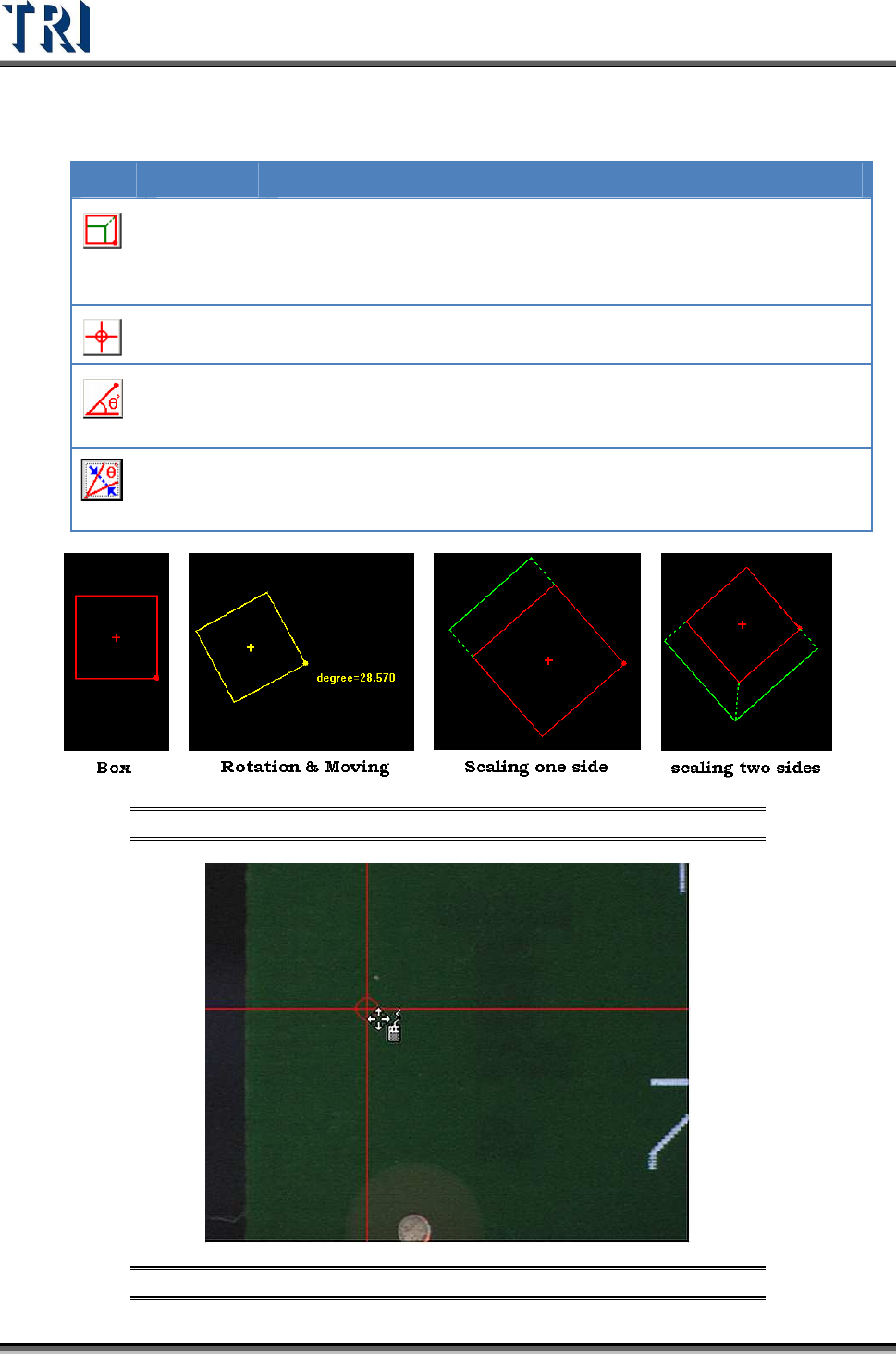
Box
The Box tool defines the coordinates of components. Click on
the Box button then a box tool will appear. The box can be
moved, rotated and resized using the mouse. The system will
set the center of the box as the component center.
Cross line
The Cross Line tool defines the coordinates of components. The
system will set the center of the cross as the component center.
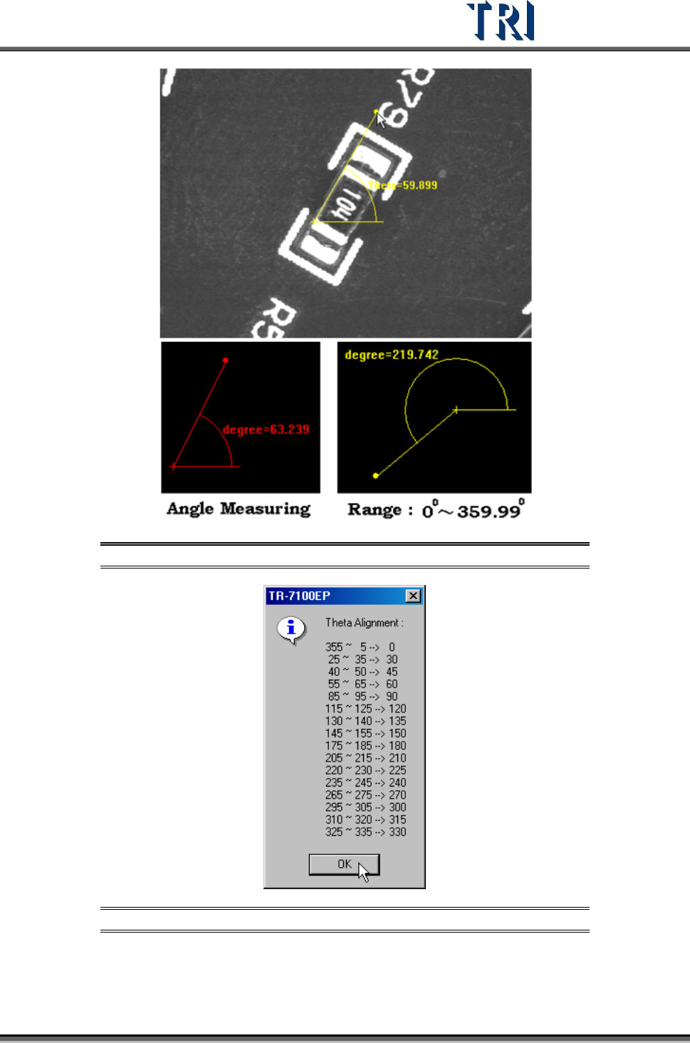
Angle
Measuring
The Angle Measuring tools defines the angle of components.
Use this to measure the rotation of components with special
angles
Theta
Alignment
The Angle Measuring tool produces a number with a decimal.
The Theta Alignment tool is used to adjust the angle to be a
rounded integer.
Figure 125: Box Tool Examples
Figure 126: Cross Line Tool Example
Test Research Inc.
TR7500 Series User Guide –Software v.2.9.0 73
Figure 127: Angle Measuring Tool Example
Figure 128: Theta Alignment Window