TR7500_Series_Software_v29_En - 第96页
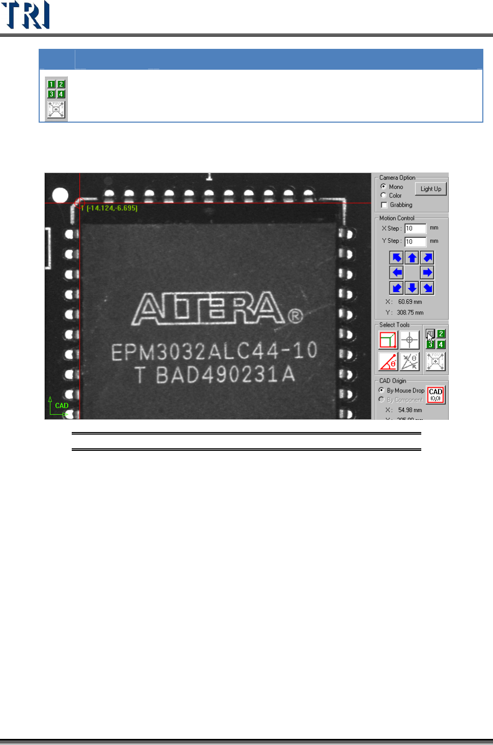
Test Research Inc. 74 TR7500 Series User Guide – Software v.2.9.0 ICON NAME DESCRIPTION Large Component Tool A tool to define the coo r dinates o f components. If the component size is lar g er than an FOV , use this too…
Test Research Inc.
TR7500 Series User Guide –Software v.2.9.0 73
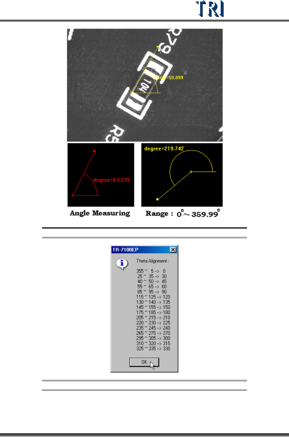
Figure 127: Angle Measuring Tool Example
Figure 128: Theta Alignment Window
Test Research Inc.
74 TR7500 Series User Guide –Software v.2.9.0
ICON
NAME DESCRIPTION
Large
Component
Tool
A tool to define the coordinates of components. If the
component size is larger than an FOV, use this tool to get the
center of the component.
Step1. Move the cross line tool to the upper-left corner of the component and
press [1] to get the first corner position.
Figure 129: Large Component Tool, Step 1
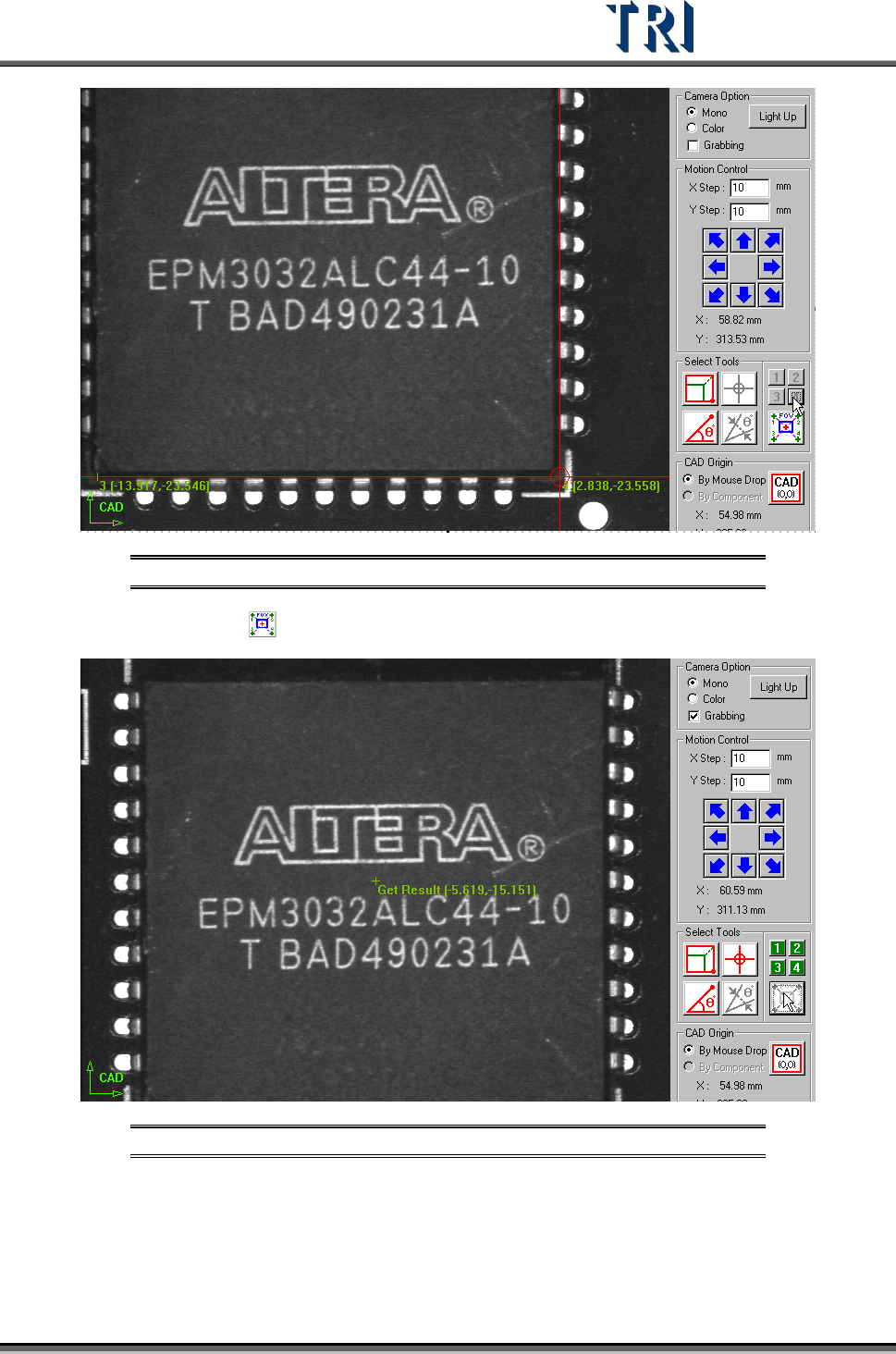
Step2. Move the cross line tool to other corners and press [2], [3] and [4]
respectively to get the coordinates with the same method.
Test Research Inc.
TR7500 Series User Guide –Software v.2.9.0 75
Figure 130: Large Component Tool, Step 2
Step3. Press and the system will calculate the component center automatically.
Figure 131: Large Component Tool, Result
Step4. Press [Add] to add the component after input relevant information.
(4) [CAD Origin] - Set the origin first for reference before building the component CAD
data. A yellow right angle icon will flash at the lower-left corner to show the origin has
not been set yet. If the origin has already been established the icon is changed to green