m330_01_gas_cabinet气柜 - 第10页
GAS SYSTEM Power supply 115/220/240 Volt, 50/60 Hz Build-in Separate Separate Separate Separate Graphic display Flow screen TSCII TSCII or Touchscreen TSCII or Touchscreen Process Control Optional Digital Process Control…
GAS SYSTEM
GAS CABINET REFERENCE MANUAL
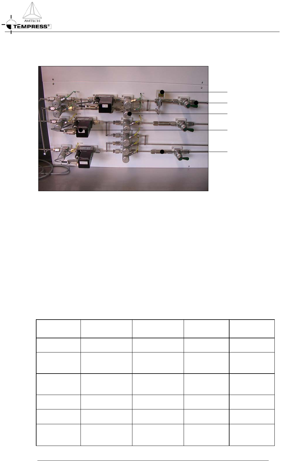
Gaspanels
Digital pressure switch
Mass Flow Controlle
r
Pneumatic valve
Manual shut-off valve
Inline gasfilte
r
Figure 2-2 LPCVD Gaspanel and components
The design of a gaspanel is dedicated to a particular process (refer to section 2.3) and must be
used accordingly. It contains all necessary components to distribute the required gasflows in a
safe and reliable manner.
The gassystem including its gaspanel is vertically mounted by default. A vertically mounted
gaspanel allows disassembling of a process tube from the rear (greyroom).
Note: Vertical gaspanels are always orbital welded.
Four gaspanelmodels are defined as default concepts. See Table 2-1 for details.
Table 2-1 Gaspanel models
Model Nr. 1 2 3 4
(Tempress
Standard)
Piping
SS 316L SS 316 L SS 316L SS 316L
Welding
Heli-arc Heli-arc Heli-arc Orbital/Butt
weld
Flow control
Flowmeter Mass Flow
Controller
Mass Flow
Controller
Mass Flow
Controller
Couplings
Swagelok Swagelok VCR VCR
Filters
Millipore Millipore
Valves
Skinner/Solenoid Skinner/Solenoid Air or N
2
operated Nupro
Air or N
2
operated Nupro
2-4

GAS SYSTEM
Power supply
115/220/240
Volt, 50/60 Hz
Build-in
Separate Separate Separate Separate
Graphic
display
Flow screen TSCII TSCII or
Touchscreen
TSCII or
Touchscreen
Process
Control
Optional Digital
Process
Controller
Digital Process
Controller
Digital Process
Controller
Digital Process
Controller
Model series 1: general features
• Very reliable and simple systems. Complete self-contained with flow schematic and
LED display showing actuation of the solenoid valves.
• Additional safety systems located at the interconnection board include: a safety board,
a pressure interface board and a High/Low limit board.
Optional items:
• Electronic Interconnection board for fully automatic control with DPC.
• Remote Control by Touchscreen or TSC-2 with graphic display, mounted remotely
from the gassystem.
Model series 2: general features
• Gastray construction with swing-out, swing-down doors for easy access to all
components.
• Electronic hardware is located in a separate compartment in the gascabinet.
• The power supply is a separate unit.
• Graphic Display is delivered as a separate unit with flatcable connections or
incorporated in Touch Screen.
Model series 3:
The same as series 2, however for systems where higher performance concerning
contamination is required, VCR instead of Swagelok and point of use filters are used.
Model series 4 (Tempress standard):
These systems meet the highest requirements concerning low contamination and
serviceability. All connections are orbital/butt welded. Electronic hardware is build into a
separate compartment in the gas cabinet.
Testing in the factory
All gaspanels are functionally tested and helium leak checked.
GAS CABINET REFERENCE MANUAL
2-5
GAS SYSTEM
GAS CABINET REFERENCE MANUAL
Manual shut-off valve
With the Manual shut-off valve (Figure 2-2) individual gaslines can be closed. Typically only
closed during maintenance activities, otherwise always open. Ball valves should only be used
fully open or fully closed.
Pneumatic valve
On the gaspanels model 3 and 4 only pneumatic controlled valves are used (see Figure 2-2).
Electronic controlled valves could introduce risks of explosion or fire in a gascabinet with
reactive gas environments and are therefore not used. On request pneumatic valves can be
operated with N
2
instead of air.
Fine metering valve
A Fine Metering Valve (FMV) is a hardware component that is used for LPCVD processes
to supply an adjustable N
2
purge flow for standby condition and reduction of the pressure
overshoot from the pressure control valve.
Check valve
Check valves are used in atmospheric processes to avoid backstreaming of blend gases. They
are normally located where Nitrogen and/or Oxygen blend with other process gasses. The
check valve allows the gasflow in only one direction to avoid backflow of the mixed process
gas.
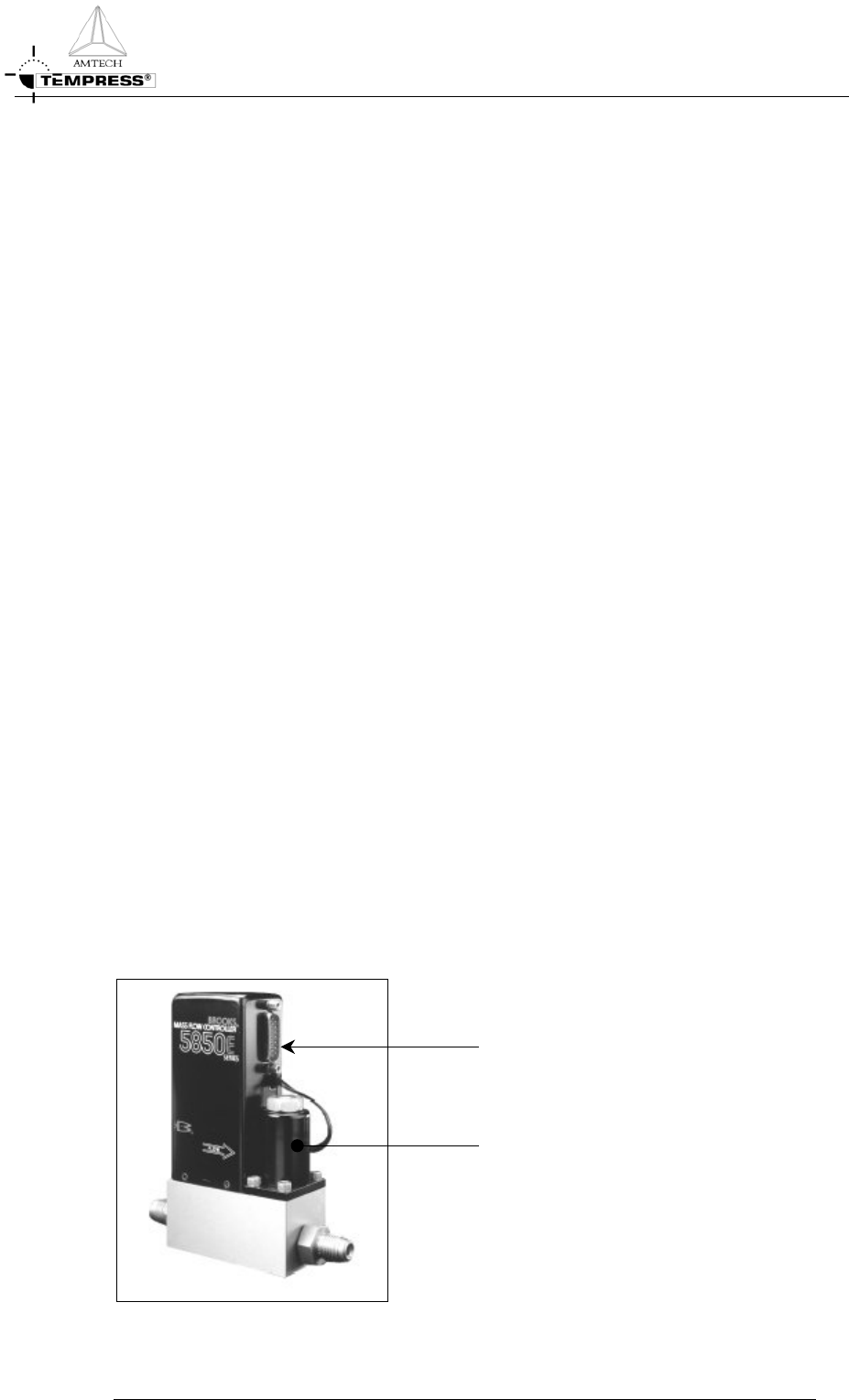
Mass Flow Controllers
A Mass Flow Controller (Figure 2-3)accurately measures and controls gasflows. The heart of
the MFC control system is the flowsensor that contains 2 temperature sensor and 1 heating
element. A power supply directs heat to the midpoint of the sensor tube. On the same tube
equidistant upstream and downstream of the heat input are resistance temperature measuring
elements. With no flow the heat reaching each temperature element is equal. With increasing
flow the flowing stream carries an increasing amount of heat towards the downstream
element and away from the upstream element. An increasing temperature difference develops
between the two elements. This difference is proportional to the amount of gas.
Electronics
Control valve
Figure 2-3 Mass Flow Controller (example)
2-6