m330_01_gas_cabinet气柜 - 第12页
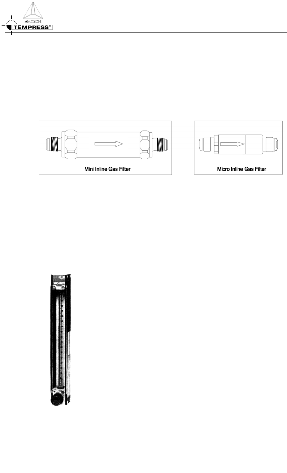
GAS SYSTEM G AS CABINET R EFERENCE M ANUAL Mini and Micro Inline Gas Filters Mini and micro inline gas fil ters are designed fo r flow rates u p to 100 slm (3.5 scfm) and are usually installed in bulkhead areas. Mini fil…
GAS SYSTEM
GAS CABINET REFERENCE MANUAL
Manual shut-off valve
With the Manual shut-off valve (Figure 2-2) individual gaslines can be closed. Typically only
closed during maintenance activities, otherwise always open. Ball valves should only be used
fully open or fully closed.
Pneumatic valve
On the gaspanels model 3 and 4 only pneumatic controlled valves are used (see Figure 2-2).
Electronic controlled valves could introduce risks of explosion or fire in a gascabinet with
reactive gas environments and are therefore not used. On request pneumatic valves can be
operated with N
2
instead of air.
Fine metering valve
A Fine Metering Valve (FMV) is a hardware component that is used for LPCVD processes
to supply an adjustable N
2
purge flow for standby condition and reduction of the pressure
overshoot from the pressure control valve.
Check valve
Check valves are used in atmospheric processes to avoid backstreaming of blend gases. They
are normally located where Nitrogen and/or Oxygen blend with other process gasses. The
check valve allows the gasflow in only one direction to avoid backflow of the mixed process
gas.
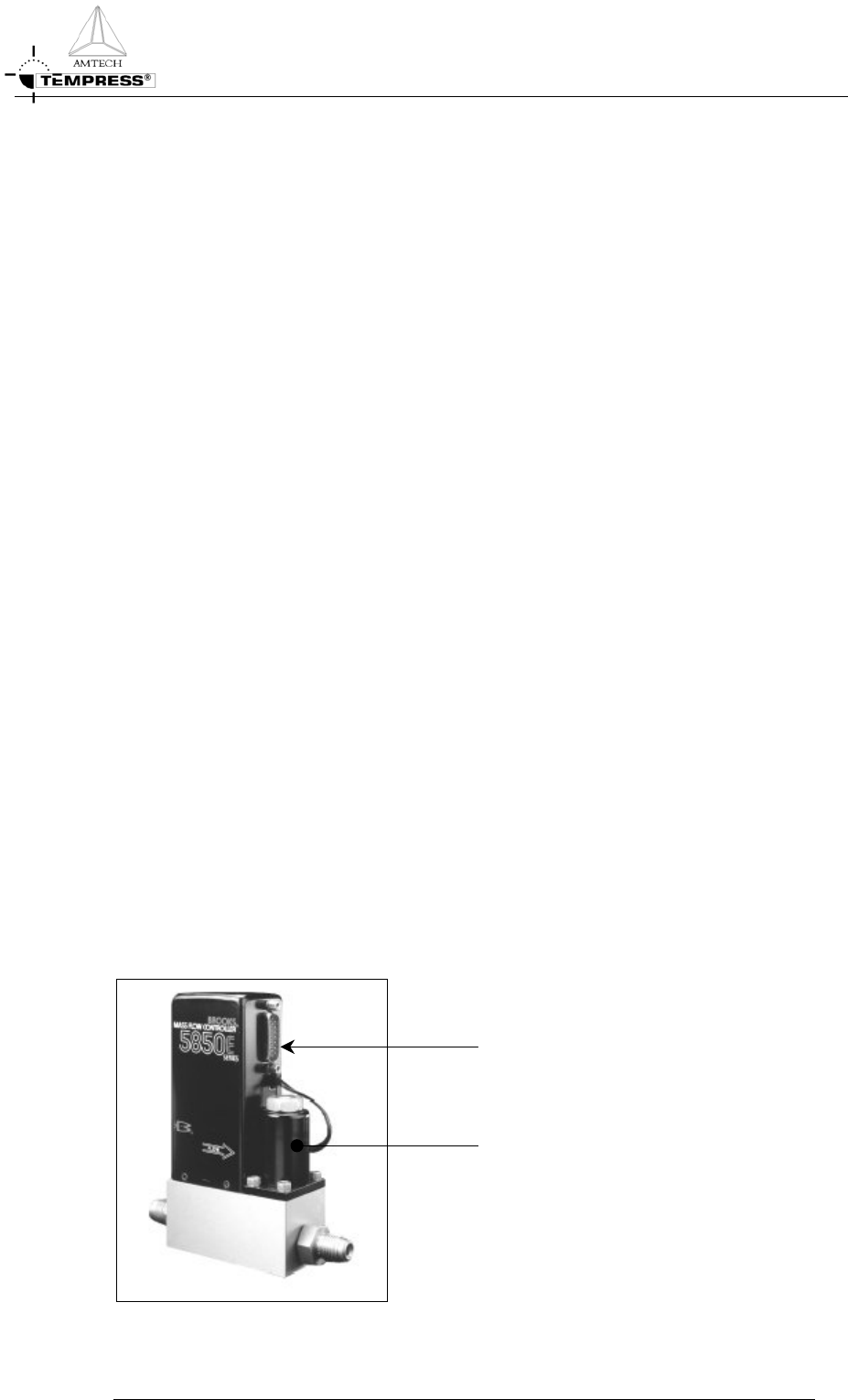
Mass Flow Controllers
A Mass Flow Controller (Figure 2-3)accurately measures and controls gasflows. The heart of
the MFC control system is the flowsensor that contains 2 temperature sensor and 1 heating
element. A power supply directs heat to the midpoint of the sensor tube. On the same tube
equidistant upstream and downstream of the heat input are resistance temperature measuring
elements. With no flow the heat reaching each temperature element is equal. With increasing
flow the flowing stream carries an increasing amount of heat towards the downstream
element and away from the upstream element. An increasing temperature difference develops
between the two elements. This difference is proportional to the amount of gas.
Electronics
Control valve
Figure 2-3 Mass Flow Controller (example)
2-6
GAS SYSTEM
GAS CABINET REFERENCE MANUAL
Mini and Micro Inline Gas Filters
Mini and micro inline gas filters are designed for flow rates up to 100 slm (3.5 scfm) and are
usually installed in bulkhead areas. Mini filters are normally used in the pre-plumbing and
micro filters on gaspanels. Teflon
®
PTFE membrane on a Teflon PFA support eliminates
downstream shedding and provides full compatibility with all process gases.
Functionally gas passes through the inlet around the filter core through the membrane. Inlet
gas is isolated from the purified outlet gas by a hermetic seal between the filter element and
the stainless steel shell.
Figure 2-4 Mini and micro inline gas filter
Flowmeters
The flowmeters are variable area flowrate indicating meters used in low cost systems. The
basic elements are a tapered glass metering tube and a metering float. Features include quick
and simple removal or installation of the tube and float while the meter remains in the
process piping.
After the flowmeter has been installed in the flowsystem it is ready for
operation. A built-in needle control valve controls the flow through the
flowmeter. These control valves are designed for fine control. Excessive
tightening may damage the valve seat and limit its effectiveness as a control
valve. If tight shut-off is required, it is recommended that a separate shut-
off valve be installed in the line immediately before the flowmeters.
Figure 2-5 Flowmeter
2-7
GAS SYSTEM
GAS CABINET REFERENCE MANUAL
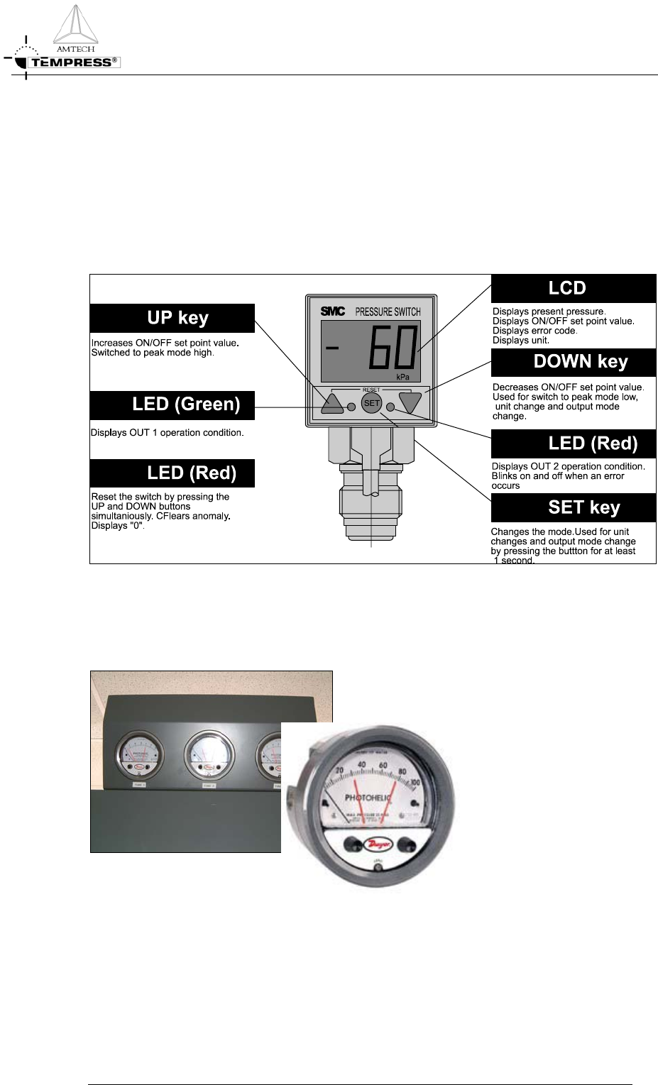
Digital pressure switch
The SMC Digital Pressure Switch is a wide pressure range device with High and Low alarm
limits. It is used to monitor N
2
supply pressure and to activate the (optional) LPCVD
baratron isolation valve. The diaphragm design prevents the sensor to directly contact fluid
media.
The calibration data is stored in an EEPROM. The EEPROM is rated to keep its memory
for 100,000 hours without having power supplied.
Figure 2-6 SMC digital pressure switch
Photohelic
Figure 2-7 Photohelic with high and low alarm limits
The photohelic is normally mounted above the gaspanels at the front of the gas cabinet. It is
a repeatable differential pressure switch with an analog pressure gauge. Switch setting can be
adjusted with large external knobs on the gauge face. The gauge reading is unaffected by the
switch operation – it will indicate accurately even if power is interrupted. This model
provides both low and high limit control.
2-8