m330_01_gas_cabinet气柜 - 第15页
GAS SYSTEM will maintain the temperatu re of the source chemical i n the Bubbler within ±0.2 0 C of the selected temperature. Schumacher ATCS bubbler system incl ude standard temperature range (POCl 3 , TMB), high temper…
GAS SYSTEM
GAS CABINET REFERENCE MANUAL
Bubbler systems
Bubbler systems are used to deliver liquid sources such as POCl
3
, TMB, TransLC
®
or DCE,
to atmospheric or LPCVD process tubes. Carrier gas pick-up can be used for atmospheric
tubes while direct evaporation is used for LPCVD tubes.
Any brand and type of bubbler system can be used to match customer needs such as
Schumachers ATCS or Komatsus etc. Bubbler systems must be designed for the particular
chemical and application.
Schumacher ATCS bubbler system
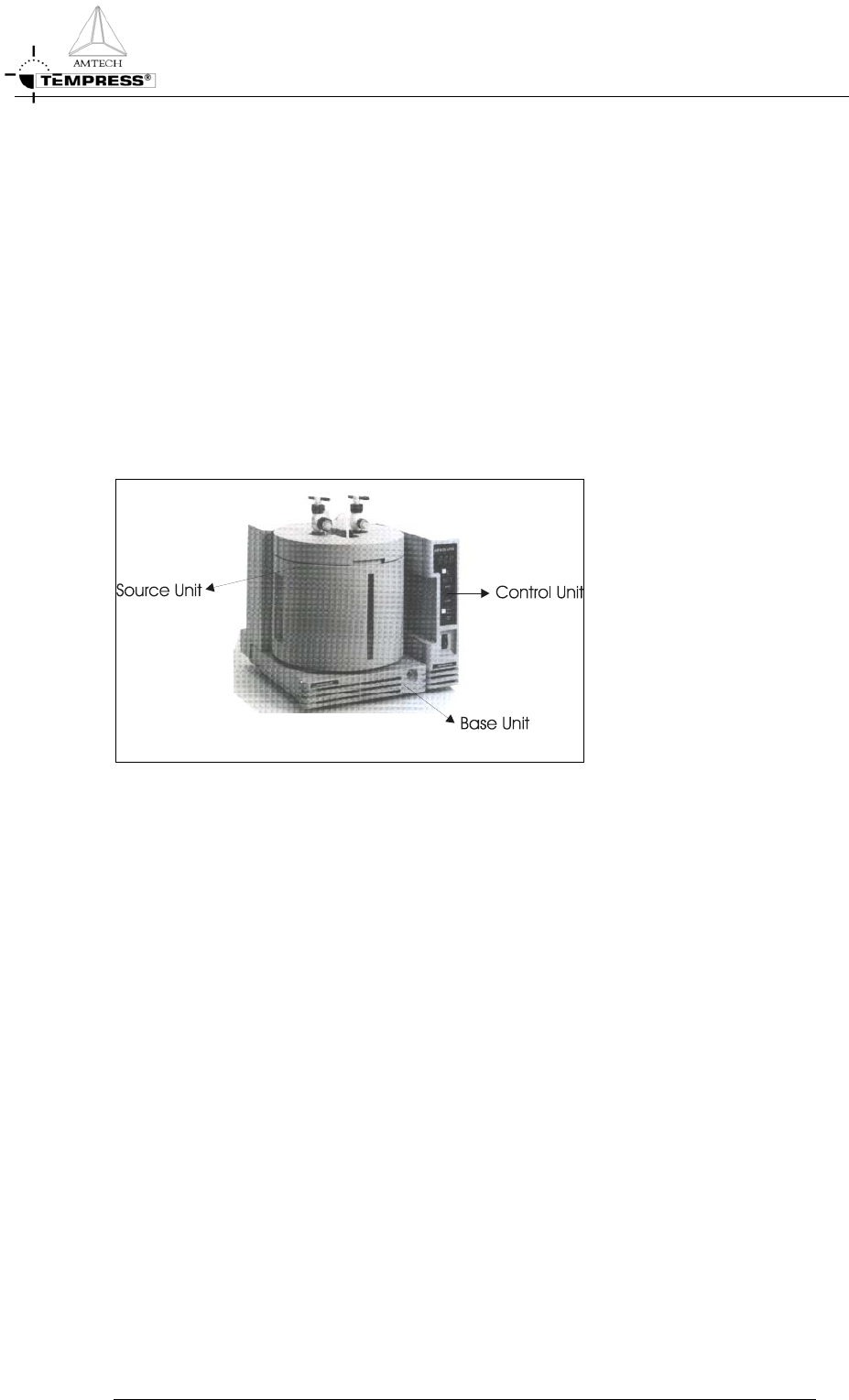
The Schumacher ATCS Temperature Controller is a micro-processor based temperature
control system for accurate and stable temperature control of liquid source chemicals. It
consists of a Base Unit, a Source Unit and a Control Unit.
Figure 2-8 Schumacher ATCS bubbler system
The Bubbler containing the chemical is placed in the Source Unit. The Source Unit allows for
easy access, installation, maintenance, and replacement of the Bubblers. The Source Unit is
equipped with a power-connecting socket for connection to the Base Unit, a four segment
level sensor and window to allow visual inspection of the Bubbler level. The Source Unit can
be removed from the Base Unit and be placed in an exhaust hood for added safety during
replacement of Bubblers.
The Base Unit accommodates the Source Unit and provides the interface between the Source
Unit and the Control Unit. The Base Units are equipped with coolers, heaters and a
temperature-sensing probe. The heater offsets the effect of the cooler to attain the
temperature within the specified range. A multiple conductor cable connects the Base Unit to
the Control Unit, providing current paths for the cooler, heater, temperature probe and level
sense. The push button on the front illuminates the back light to view the liquid level
through the window on the Source Unit.
The Control Unit provides the electrical power and necessary current control to maintain a
selected temperature and, therefore, constant vapor pressure within the Bubbler. The front
panel controls consist of an ON/OFF power switch, an audio defeat, and mode selection
push button. The Control Unit furnishes a regulated voltage for the cooler. Voltage pulses at
varying rates to the heater. Thus, an average power level is established in the Base Unit that
2-9

GAS SYSTEM
will maintain the temperature of the source chemical in the Bubbler within ±0.2
0
C of the
selected temperature.
Schumacher ATCS bubbler system include standard temperature range (POCl
3
, TMB), high
temperature range (TEOS) and TransLC specific models.
GAS CABINET REFERENCE MANUAL
2-10
GAS SYSTEM
Trans-LC
®
bubbler system
The Trans 1,2 Dichloroethylene (Trans-LC
®
) is an Schumacher ozon-safe liquid chlorine
source in silicon oxidation and tube cleaning. For more information about the properties and
applications of TransLC
®
see the process manual.
The Trans-LC bubbler system consists of the following components:
• Trans-LC System
• Source System
• Base System
• Control Unit
The ATCS-TLC is modified to fit the Trans-LC properties. The Source unit (ATCS) is
equipped with an over temperature cut-out switch in the TLC model. The temperature
setpoint is hardware limited to a range of 10
0
C to 22
0
C.
The temperature alarm window is opened from the standard +
2
0
C to + 5
0
C.
The Schumacher Smart Probe is included. This probe system prevents the Bubbler from
being installed in the incorrect orientation that may interfere with the level sensing system.
The probe system also generates a temperature alarm and prevents the heater from operating
if the temperature probe is not fully inserted through the front insulation cover hole and into
the Bubbler.
Potential spark sources are removed from both the Source Unit and Basic Unit. These units
are suitable for use in an area where Trans-LC vapors may be present. The Control Unit does
not have spark or ignition sources removed and therefore must be located in an area where
explosive vapors are not present.
WARNING: EXPLOSION HAZARD. Spark or ignition
sources are present in the Control Unit. The user must ensure that
the Control Unit is located in an area where explosive vapors are
not present. Under no circumstances should electrical connectors be
connected or disconnected while the equipment is energized.
External torches
The Tempress Standard External Torch is compromised of a water-cooled stainless steel shell,
which contains a quartz balloon (in which the steam will be produced), a mixer-assy, a ball-joint
and a heating element. It generates high purity steam, without detrimental effects on the
temperature profile of the furnace. The location of the external torch is in the gassource
cabinet. A thermocouple is inserted in the inner tube of the mixer assy. O
2
and H
2
are fed
separately into the mixer-assy and are heated above 750
0
C. When the gases are mixing in the
quartz balloon, the H
2
ignites spontaneously and water vapour is produced. The torch
temperature is regulated by a digital temperature controller. For more detailed information see
the enclosed “External Torch Manual
”.
GAS CABINET REFERENCE MANUAL
2-11