m330_01_gas_cabinet气柜 - 第5页
INTRODUCTION 1.Introduction 1.1 Scope of the manual This manual ex plains how to insta ll, adjust or ma intain the Tempress System s Inc. gascabinet , including its gassystem and all pe ripheral equipment and part s desc…

LIST OF FIGURES
List of figures
Figure 1-1 Tempress L-shaped Gascabinet ............................................ 1-1
Figure 2-1 Source gas pressure adjustment ........................................... 2-3
Figure 2-2 LPCVD Gaspanel and components ....................................... 2-4
Figure 2-3 Mass Flow Controller example............................................... 2-6
Figure 2-4 Mini and micro inline gas filter................................................ 2-7
Figure 2-5
Flowmeter .............................................................................. 2-7
Figure 2-6 SMC digital pressure switch................................................... 2-8
Figure 2-7 Photohelic with high and low alarm limits............................... 2-8
Figure 2-8 Schumacher ATCS bubbler system ....................................... 2-9
Figure 2-9 Coldtrap (small design) ........................................................ 2-12
Figure 2-10 Cooling Spiral tube with Ammonium chloride (NH
4
Cl) deposit2-
13
GAS CABINET REFERENCE MANUAL
I
V
INTRODUCTION
1.Introduction
1.1 Scope of the manual
This manual explains how to install, adjust or maintain the Tempress Systems Inc. gascabinet,
including its gassystem and all peripheral equipment and parts descriptions. For technical
instructions and descriptions concerning the DPC refer to the DPC reference manual
(M410.00). Before starting up, installing, operating and/or maintaining the complete gascabinet
it is mandatory to read this manual first.
1.2 Overview
The gascabinet is part of the Tempress Systems Inc. diffusion furnace. It contains all process
gas facilities as well as the Digital Process Controller (DPC) and peripheral equipment. The
standard L-shape cabinet can be replaced by a backmounted cabinet in case of limited space.
Normally the gascabinet will be placed in the grey-room.
unted cabinet in case of limited space.
Normally the gascabinet will be placed in the grey-room.
Place for
Peripheral equipment
Process gas facilities
DPC
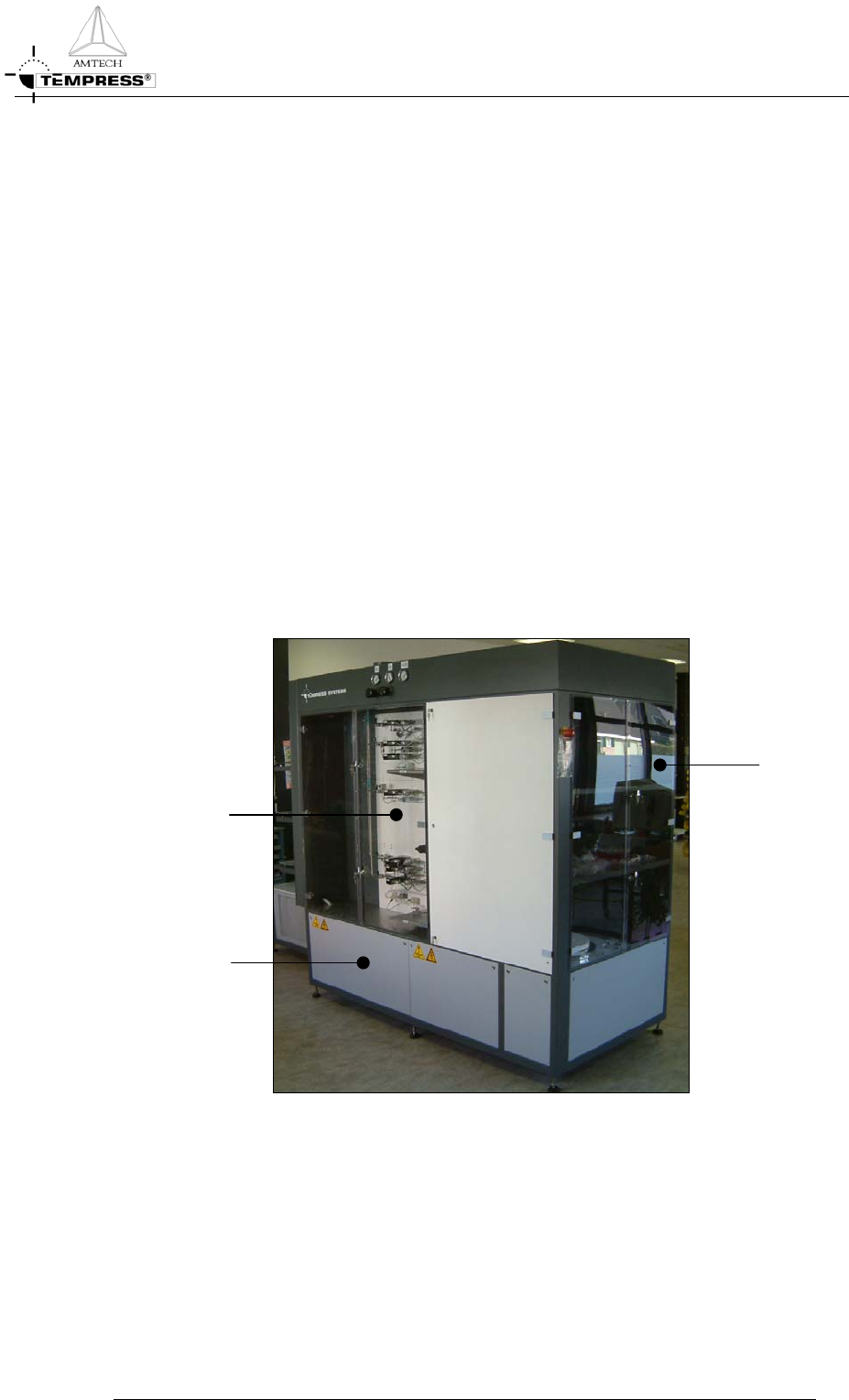
Figure 1-1 Tempress L-shaped Gascabinet
The Tempress Systems Gas cabinets are designed for easy access to all components and
shielded with Plexiglas doors, see Figure 1-1. The cabinets are made of heavy gauge steel with
a polyurethane finish. The gas cabinet is exhausted through the full height of the cabinet. The
space saving vertically mounted gassystems offer additional space for accessory units, such as
external torch and bubbler systems, and easy tube exchange from the rear. The flexible gas
cabinet design, in combination with the small footprint furnaces, makes the Tempress
Systems furnaces adaptable to most cleanroom layouts.
GAS CABINET REFERENCE MANUAL
1-1
GAS SYSTEM
2. Gas System
The gassystem is defined as the complete gas supply. It includes preplumbing, gaspanels and
electronic components. The gassystems provide the desired flows of (a mixture of) gasses
required for the different kind of processes. Each process has its own gassystem.
The gas cabinet of a furnace can contain any of the following components, which will be
described in the following sections.
• Pressure Gauges
• Pressure Regulators
• Gaspanels
Manual shut-off valve
Pneumatic valve
Fine metering valve
Check valve
Mass Flow Controllers
Mini and Micro Inline Gas Filters
Flowmeters
GAS CABINET REFERENCE MANUAL
2-1