m330_01_gas_cabinet气柜 - 第9页
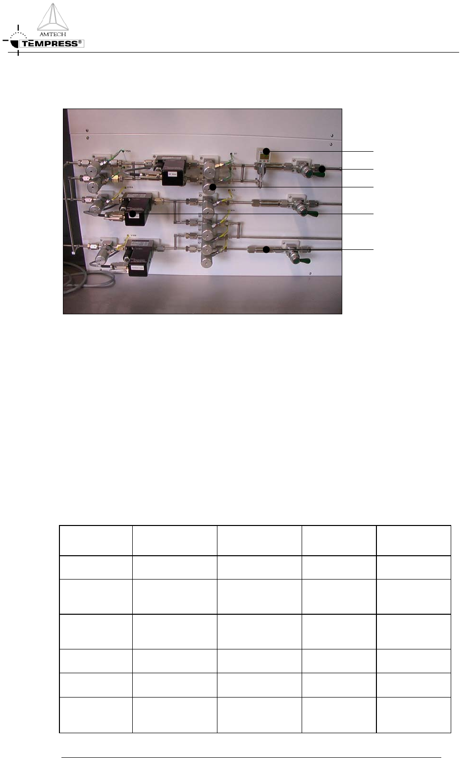
GAS SYSTEM G AS CABINET R EFERENCE M ANUAL Gaspanels Digital pressure switc h Mass Flow Controlle r Pneumatic valve Manual shut-off valve Inline gasfi lte r Figure 2-2 LPCVD Gaspanel and components The design of a gaspan…
GAS SYSTEM
GAS CABINET REFERENCE MANUAL
2.1 Gassystem parts
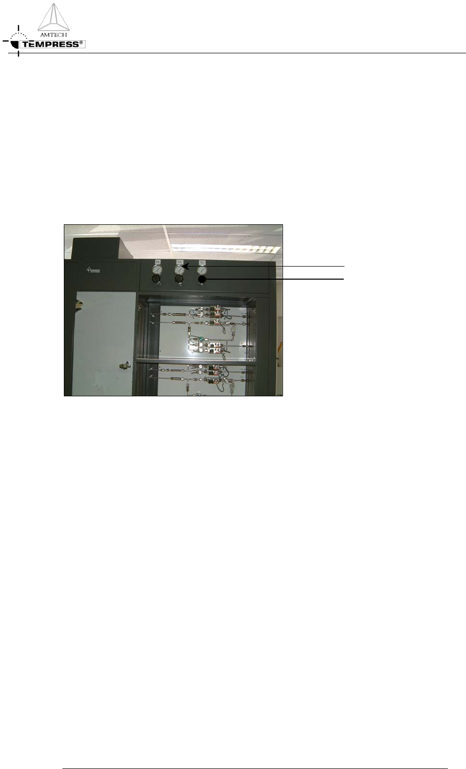
Pressure Gauges
The pressure gauge is used for readout of the process gas pressure before the gas is
distributed to the gaspanels. It is designed with safety features to minimize injury to
personnel and damage to property in the event of a gauge failure. The gauges are mounted
above the gassystems at the front of the gascabinet.
Pressure Gauge
Pressure Regulator
Figure 2-1 Source gas pressure adjustment
Pressure Regulators
Each process gas has its own regulator to reduce the gassource pressure and adjust the
correct pressure to the gassystem. The pressure regulators are part of the pre-plumbing and
are located above the gaspanels, see Figure 2-1.
2-3
GAS SYSTEM
GAS CABINET REFERENCE MANUAL
Gaspanels
Digital pressure switch
Mass Flow Controlle
r
Pneumatic valve
Manual shut-off valve
Inline gasfilte
r
Figure 2-2 LPCVD Gaspanel and components
The design of a gaspanel is dedicated to a particular process (refer to section 2.3) and must be
used accordingly. It contains all necessary components to distribute the required gasflows in a
safe and reliable manner.
The gassystem including its gaspanel is vertically mounted by default. A vertically mounted
gaspanel allows disassembling of a process tube from the rear (greyroom).
Note: Vertical gaspanels are always orbital welded.
Four gaspanelmodels are defined as default concepts. See Table 2-1 for details.
Table 2-1 Gaspanel models
Model Nr. 1 2 3 4
(Tempress
Standard)
Piping
SS 316L SS 316 L SS 316L SS 316L
Welding
Heli-arc Heli-arc Heli-arc Orbital/Butt
weld
Flow control
Flowmeter Mass Flow
Controller
Mass Flow
Controller
Mass Flow
Controller
Couplings
Swagelok Swagelok VCR VCR
Filters
Millipore Millipore
Valves
Skinner/Solenoid Skinner/Solenoid Air or N
2
operated Nupro
Air or N
2
operated Nupro
2-4

GAS SYSTEM
Power supply
115/220/240
Volt, 50/60 Hz
Build-in
Separate Separate Separate Separate
Graphic
display
Flow screen TSCII TSCII or
Touchscreen
TSCII or
Touchscreen
Process
Control
Optional Digital
Process
Controller
Digital Process
Controller
Digital Process
Controller
Digital Process
Controller
Model series 1: general features
• Very reliable and simple systems. Complete self-contained with flow schematic and
LED display showing actuation of the solenoid valves.
• Additional safety systems located at the interconnection board include: a safety board,
a pressure interface board and a High/Low limit board.
Optional items:
• Electronic Interconnection board for fully automatic control with DPC.
• Remote Control by Touchscreen or TSC-2 with graphic display, mounted remotely
from the gassystem.
Model series 2: general features
• Gastray construction with swing-out, swing-down doors for easy access to all
components.
• Electronic hardware is located in a separate compartment in the gascabinet.
• The power supply is a separate unit.
• Graphic Display is delivered as a separate unit with flatcable connections or
incorporated in Touch Screen.
Model series 3:
The same as series 2, however for systems where higher performance concerning
contamination is required, VCR instead of Swagelok and point of use filters are used.
Model series 4 (Tempress standard):
These systems meet the highest requirements concerning low contamination and
serviceability. All connections are orbital/butt welded. Electronic hardware is build into a
separate compartment in the gas cabinet.
Testing in the factory
All gaspanels are functionally tested and helium leak checked.
GAS CABINET REFERENCE MANUAL
2-5