AX501partlist
A8. Spares , tools and materials Service Manual 4022 593 50571 A8-8 AX - series 06.01 A. SYSTEM A8.3.3 Base Item No. Part of Item No. Ordering Code Description Qty/ Mod Priority indicator Repair options Replacement Instr…
A8. Spares, tools and materials
Service Manual 4022 593 50571
A8-8 AX - series 06.01
A. SYSTEM
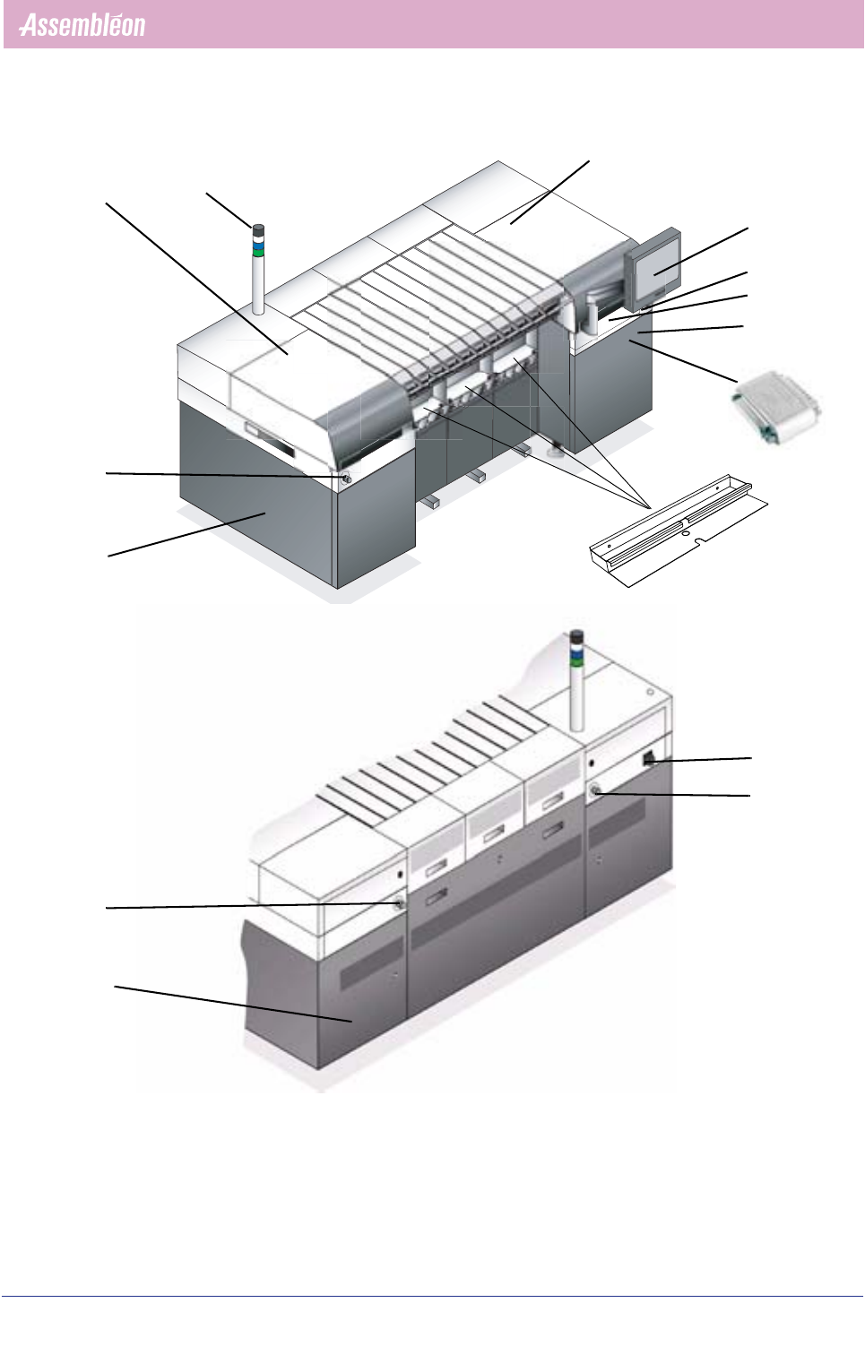
A8.3.3 Base
Item No.
Part of Item No.
Ordering Code
Description
Qty/ Mod
Priority indicator
Repair options
Replacement Instruction
Remarks
01-01 9488-396-00103 Safety Interlock 2 Y - -
01-02 9498-396-00004 Actuator key 2 Y - -
01-03 9498-396-00003 Emergency stop button 4 Y - •
01-04 9498-396-00006 Indicator green 1 - - •
01-05 9498-396-00007 Indicator white 1 - - •
01-06 9498-396-00008 Indicator blue 1 - - •
01-07 9498-396-00005 Buzzer 1 - - •
01-08 9498-396-00091 Touch screen 1 Y - -
01-09 9498-396-00093 Power supply touchscreen 1 - - -
01-11 9498-396-00067 Keyboard with touchpad 1 - - - In drawer.
01-12 9498-396-00079 Hub/Switch 1 Y - • Behind door.
01-13 9498-396-00109 Fan 2 Y - - Behind transport and system
controller.
01-14 02-01 9498-396-00026 Main switch 1 - - -
01-15 9498-396-00563 Software licence hardware key,
limited validity 300 machine hours.
1 Y - • Behind door. Refer to B8.2.4
9498-398-00563 Software licence hardware key 1 Y RC • Behind door. Refer to B8.2.4
01-16 9498-396-01149 Component bin 3/5 - - • Only applicable in case
upgraded FCM feeder trolleys
are used.
4022 593 50571 Service Manual
06.01 AX - series A8-9
A8. Spares, tools and materials
A. SYSTEM
01-01
01-02
01-03
01-04
01-05
01-06
01-07
01-08
01-09
01-11
01-12
01-13
01-14
01-03
01-03
01-03
01-01
01-02
01-15
01-13
01-16
A8. Spares, tools and materials
Service Manual 4022 593 50571
A8-10 AX - series 06.01
A. SYSTEM
A8.3.4 Mains supply unit
Item No.
Part of Item No.
Ordering Code
Description
Qty/ Mod
Priority indicator
Repair options
Replacement Instruction
Remarks
02-01 9498-396-00090 Mains supply unit 1 Y - • Main switch (01-14)
included
02-02 9498-396-00022 Monitor relay 3 phase 1 Y - •
02-03 9498-396-00029 Power supply 24V 1 Y - • Also in transport controller
02-04 9498-396-00027 Safety relay 24V 1 Y - • Also in transport controller
02-05 9498-396-00023 Circuit breaker 8A 1 ph 6 Y - •
02-06 9498-396-00024 Circuit breaker 4A 1 ph 2 Y - •
02-07 9498-396-00025 Circuit breaker 4A 3 ph 2 Y - •
02-08 9498-396-00028 Fan 1 Y - • On rear side of mains
supply unit.
02-09 9498-396-00111 Relay 1 Y - •
02-10 9498-396-00152 Diode 1 Y - • Behind components