00193325-01.pdf - 第18页
2 Introduction and basic terms SIPLA CE Sof tware Guide SR.503.xx 2.2 Overview Issue 12/01 EN 18 A station may exist as part of a l ine or m ay be t he only m achin e in a li ne. 2 Each station has a „station compute r“ …
SIPLACE Software Guide SR.503.xx 2 Introduction and basic terms
Issue 12/01 EN 2.2 Overview
17
2
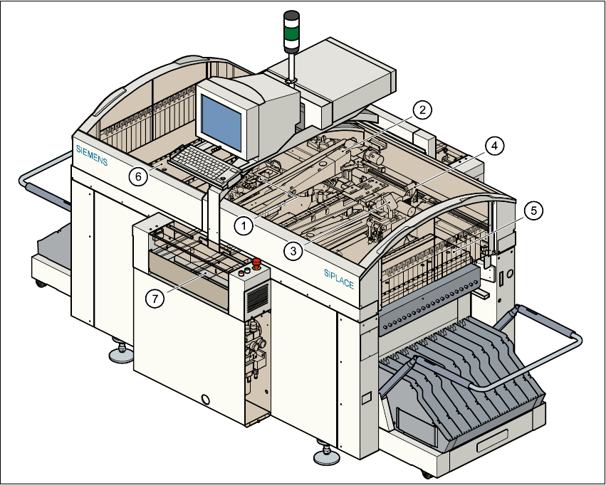
Fig. 2.2 - 2 Diagram showing an overview of a component placement machine (e.g. the S25-HM)
Key to Fig. 2.2 - 2
(1) 6/12-segment, Collect&Place head with component vision module (Gantry 1)
(2) Gantry 1 with PCB vision module
(3) 6/12-segment, Collect&Place head with component vision module (Gantry 2)
(4) Gantry 2 with PCB vision module
(5) Stationary component supply (Location 1)
(6) Stationary component supply (Location 3)
(7) PCB conveyor (dual conveyor option)
2

2 Introduction and basic terms SIPLACE Software Guide SR.503.xx
2.2 Overview Issue 12/01 EN
18
A station may exist as part of a line or may be the only machine in a line. 2
Each station has a „station computer“ which is located on the side of the input area behind a ma-
chine base door. This area also accommodates the uninterruptible power supply (UPS). The UPS
is available as an option.
2
A monitor with touch screen and retractable keyboard with an integrated trackball is mounted on
either side (HS-50 only) of the station (see Figures 2.2 - 1 and 2.2 - 2). 2
NOTE
You can operate the station computer software either via the keyboard and trackball or via the
touch screen. 2
SIPLACE Software Guide SR.503.xx 2 Introduction and basic terms
Issue 12/01 EN 2.2 Overview
19
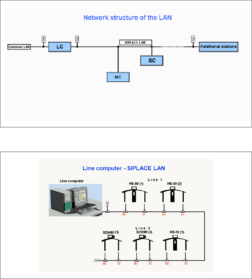
2.2.2 Overview of the system components that make up a SIPLACE line
2
Fig. 2.2 - 3 Diagram showing the network structure of the LAN
2
Fig. 2.2 - 4 Schematic diagram of the network in a SIPLACE line (example)
The individual stations obtain their placement data from a host computer (Line computer UNIX or
Siplace Pro). The placement data is sent to the individual stations by the job control function of
the host computer. 2