00193325-01.pdf - 第21页
SIPLACE S oftware Guide SR.503.xx 3 Graphical user i nterface Issue 12/01 E N 3.2 Components of t he user in terface 21 3.2 Component s of the user interface 3 Fig. 3.2 - 1 Components of the user interface (for e xample,…

3 Graphical user interface SIPLACE Software Guide SR.503.xx
3.1 Inputs and Controls Issue 12/01 EN
20
3 Graphical user interface
This section describes how to use the various controls such as the keyboard, trackball, mouse
buttons and touch screen and also introduces the functions of the individual components of the
graphical user interface. 3
In addition, the safety notes of the operating instructions for
SIPLACE HS-50 und S-25 HM machines take priority. 3
3.1 Inputs and Controls
Keyboard 3
The keyboard with its integrated trackball and mouse buttons acts as the standard input tool for
the graphical user interface of the station computer software. 3
Trackball and mouse buttons 3
You use the trackball to move the mouse pointer across the user interface to the desired object
and then use the left mouse button to select the object or execute the appropriate function. 3
Touch screen 3
The (touch) screen can also be used to operate the user interface. In this way, you can directly
select the actions, or trigger the corresponding functions, by touching the corresponding object
with your finger on screen. 3
NOTE
In this guide, triggering an action using the left mouse button or by touching the screen with your
finger is always referred to as „clicking“. 3
3
SIPLACE Software Guide SR.503.xx 3 Graphical user interface
Issue 12/01 EN 3.2 Components of the user interface
21
3.2 Components of the user interface
3
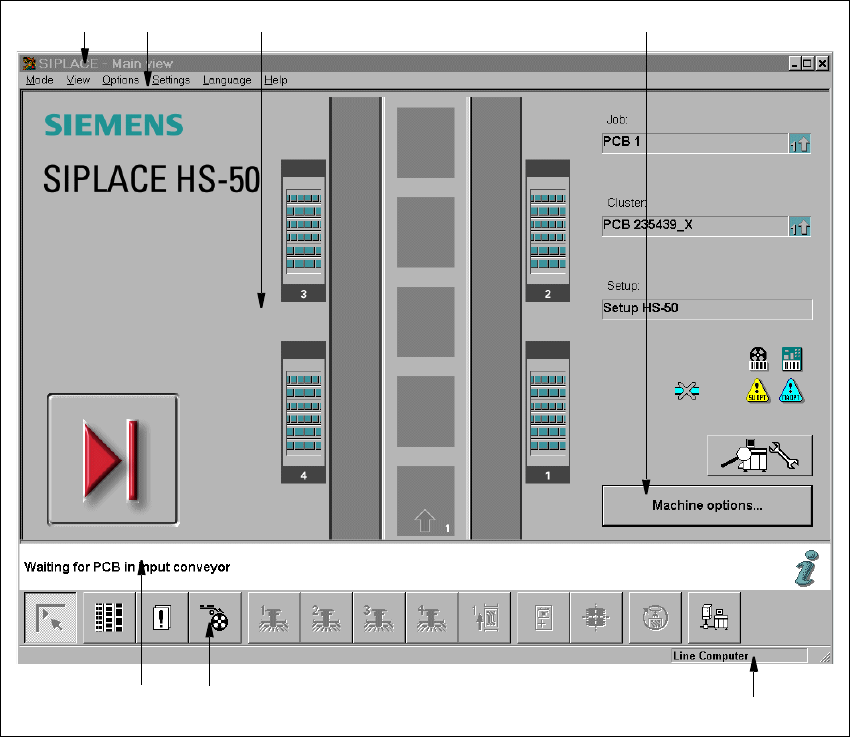
Fig. 3.2 - 1 Components of the user interface (for example, the Main view of the HS-50)
3
Key to Fig. 3.2 - 1
(1) Title bar
(2) Menu bar
(3) Working area/display area
(4) Controls
(5) Status area
(6) Toolbar
(7) Info bar
1
6
7
5
2 3 4
3 Graphical user interface SIPLACE Software Guide SR.503.xx
3.2 Components of the user interface Issue 12/01 EN
22
3
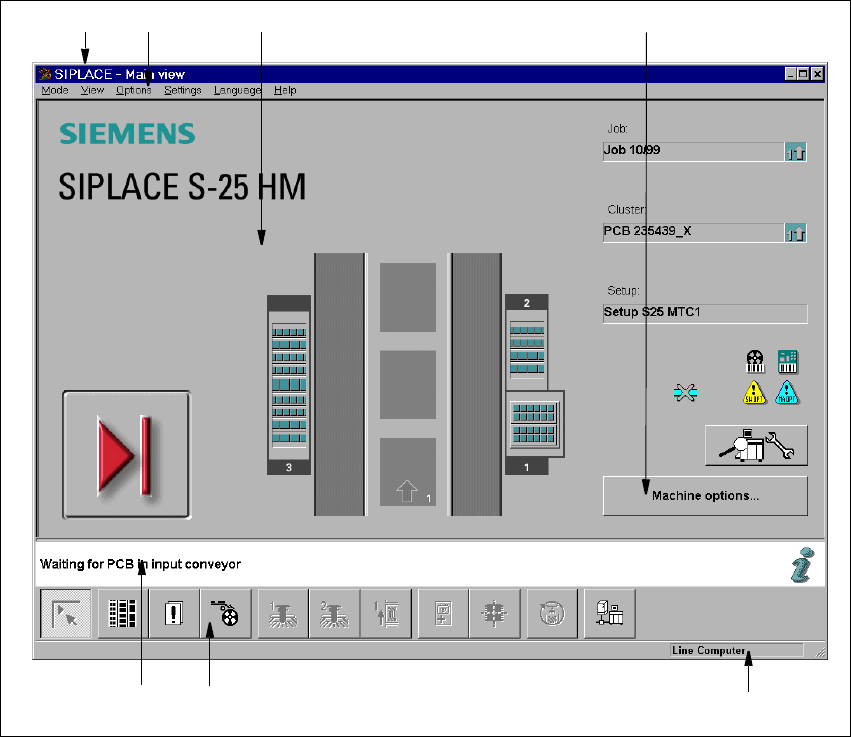
Fig. 3.2 - 2 Components of the user interface (for example, the Main view of the S-25 HM)
3
Key to Fig. 3.2 - 2
(1) Title bar
(2) Menu bar
(3) Working area/display area
(4) Controls
(5) Status area
(6) Toolbar
(7) Info bar
3
1
6 75
2 3 4