00193325-01.pdf - 第29页
SIPLACE S oftware Guide SR.503.xx 3 Graphical user i nterface Issue 12/01 E N 3.2 Components of t he user in terface 29 Check the bo x "PC B not to be a ssem bled in P A2" if the PCB is to be proce ssed on p …
3 Graphical user interface SIPLACE Software Guide SR.503.xx
3.2 Components of the user interface Issue 12/01 EN
28
3
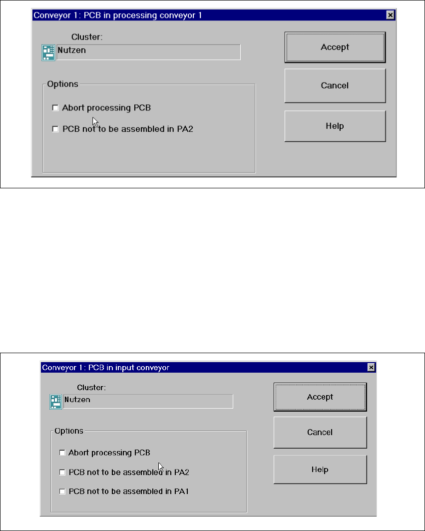
Fig. 3.2 - 6 „Conveyor 1: PCB in processing conveyor 1" dialog (Example: HS-50)
Check the box "Abort processing PCB" if the PCB is to be transported to the output conveyor
without further processing.
Check the box "PCB not to be assembled in PA2" if the PCB is to be processed on processing
conveyor 1 and is then to be transported to the output conveyor without being processed on
processing conveyor 2.
Click the Accept button.
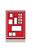
If the PCB is located on the input conveyor, the following dialog box is opened. 3
3
Fig. 3.2 - 7 "Conveyor 1: PCB in processing conveyor 1" dialog
Check the box "Abort processing PCB" if the PCB is to be transported to the output conveyor
without further processing.
SIPLACE Software Guide SR.503.xx 3 Graphical user interface
Issue 12/01 EN 3.2 Components of the user interface
29
Check the box "PCB not to be assembled in PA2" if the PCB is to be processed on processing
conveyor 1 only and is then to be transported to the output conveyor without being processed
on processing conveyor 2.
Check the box "PCB not to be assembled in PA1" if the PCB is to be transported through pro-
cessing conveyor 1 without being processed and is then to be processed on processing con-
veyor 2.
Then click the Accept button.
Processing of PCB aborted 3
If processing of the PCB has been aborted by clicking the PCB icon (see example above), the
color of the PCB icon changes to red.
The icon is also displayed in red if a PCB is manually placed on processing conveyor 1 or 2. The
PCB is thus not recognized by the system and is transported to the output conveyor. 3
3 Graphical user interface SIPLACE Software Guide SR.503.xx
3.2 Components of the user interface Issue 12/01 EN
30
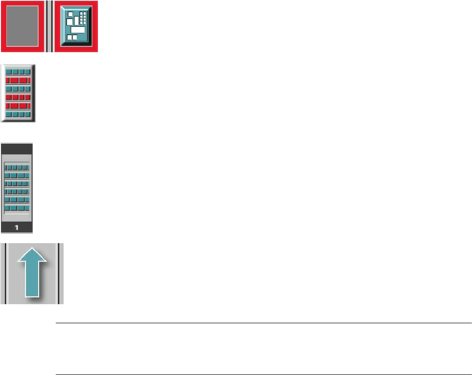
Meaning of Other Icons and Markings 3
If a track error, machine error or conveyor error occurs, then the corresponding graphic is high-
lighted in red (see examples below). 3
Examples:If an error occurs in a processing area, then this is displayed with a red
border.
You can abort processing of the PCB which is located in this area by clicking the
PCB icon.
If a conveyor error occurs during transport, this is indicated by the presence of red
bars on the left and right.
If a track error occurs (e.g. missing components), then individual parts of the
graphic which correspond to the layout of the current feeder location are displayed
against a red background. In addition, the graphic is displayed with a contour.
If you click this graphic you can use the appropriate functions to
reactivate all the tracks for this location. 3
Machine error (Emergency stop) 3
3
3
Components missing at location 3
3
3
3
3
Feeder location full 3
3
3
Conveyor set to "Transport through" 3
NOTE
This means that the „Process PCB“ function is deactivated in the machine options.
The PCBs are passed through the entire transport process without being processed. 3
3