00193325-01.pdf - 第32页
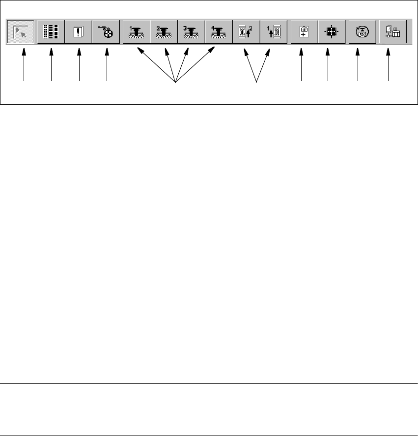
3 Graphical user int erface SIPLACE Software Guide SR.503.xx 3.2 Components of the user interface Issue 12/01 EN 32 3.2.2 T oolbar in Main vie w 3 Fig. 3.2 - 8 T oolb ar in Main view 3 Key to Fig. 3.2 - 8 (1) Main vi ew …

SIPLACE Software Guide SR.503.xx 3 Graphical user interface
Issue 12/01 EN 3.2 Components of the user interface
31
(green) starts the context-sensitive help system for the current view 3
3
(red) starts the help system that offers possible causes for the current error
and suggests ways to eliminate the error. 3
3
Once the error has been eliminated successfully, the current error is deleted. 3
3
The machine options have been changed. 3
3
The software options have been changed. 3
3
Barcode-supported component refill operation. 3
3
PCB barcode is activated. 3
3
The connection to the line computer has been interrupted. It is not possible to receive
data. 3
3
Automatic compressed air is activated. 3
3
Automatic compressed air is deactivated. 3
3
Status display for the component level indicator (option). 3
3
Status display for the Traceability (Option)
Please refer to the "Manual Traceability for a detailed description. 3
3
3
3 Graphical user interface SIPLACE Software Guide SR.503.xx
3.2 Components of the user interface Issue 12/01 EN
32
3.2.2 Toolbar in Main view
3
Fig. 3.2 - 8 Toolbar in Main view
3
Key to Fig. 3.2 - 8
(1) Main view
(2) Set-up, placement functions
(3) Error, placement functions
(4) Component feeder, placement functions
(5) Gantry 1 to 4, single functions
(6) Conveyor 1 and 2, single functions
(7) Teach fiducials, vision functions
(8) Test component, vision functions
(9) Start SITEST test program
(10) GEM Interface
3
NOTES for points (6) and (10) above
The single functions for Conveyor 2 can only be called if a dual conveyor system has been con-
figured. 3
Click the required button in the toolbar.
This switches the user interface to the appropriate view.
The button corresponding to the view which is currently active itself becomes inactive.
3
1 8 9 10765432
SIPLACE Software Guide SR.503.xx 3 Graphical user interface
Issue 12/01 EN 3.3 User interface - views and menus
33
3.3 User interface - views and menus
3.3.1 Views
To perform a specific operation via the user interface, you may need to switch this to a different
view. You can do this by clicking the appropriate button on the toolbar (see section 3.2.2) or by
selecting the corresponding menu item from the „View“ menu (see section 3.3.2.2). 3
3.3.2 Menus
3.3.2.1 "Mode" menu
The complete set of functions present in the „Mode“ menu is only available in the main view.
In the views „Setup...“, „Errors...“ and „Feeders“ and their sub-views, only the menu items „Stop
processing PCB“ and „Processing PCB“ are available. In the other views, the „Mode“ menu is not
displayed. 3
NOTE
For a detailed description of the menu items „Stop processing PCB“, „Processing PCB“ and „Con-
tinue processing“, refer to section 3.2.1 since these functions are usually activated via the corre-
sponding icons in the working area. 3
3
Processing PCB 3
Assembly of the PCBs is started or continued if previously interrupted. 3
Click the Processing PCB menu item (or the corresponding icon).
3
Stop processing PCB 3
The current PCB assembly process is stopped. 3
Click the Stop processing PCB menu item (or the corresponding icon)