00193325-01.pdf - 第58页
3 Graphical user int erface SIPLACE Software Guide SR.503.xx 3.4 Flow chart for the main v iew Issue 12/01 EN 58
SIPLACE Software Guide SR.503.xx 3 Graphical user interface
Issue 12/01 EN 3.4 Flow chart for the main view
57
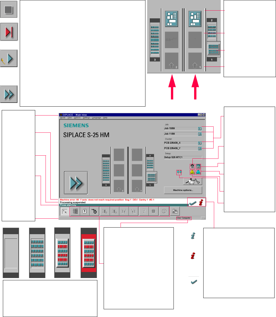
3.4 Flow chart for the main view
3
3
3
Pull-down menus
3
Error information
bar
3
Status indication
and process status
3
Notification about a
specific action to
carry out
3
Information bar
3
Control modes:
Stand alone
GEM Host (not yet available)
Line Computer
SIPLACE Pro
3
Submenu icons with info box:
Setup
Error
Feeders
Gantry 1, 2
PCB conveyor 2, 1
Teach fiducial
Test component
SITEST
GEM
3
Output conveyor
The PCB is supplied.
Central conveyor
The central conveyor is empty.
MTC on location 1
(S-25 HM only)
Input conveyor
The input conveyor is empty.
3
Context-sensitive help system
This also provides a short description of all
displayed operating elements.
3
Help system for errors
Starts a help system displaying possible
causes of the current error along with correc-
tive actions.
3
Error deletion
After the error has been successfully cor-
rected, the currently active error is deleted.
Transport 2
Transport 1
3
Identifies the job or cluster of the
right conveyor lane, or of the
single conveyor, and of the left
conveyor lane (dual conveyors
only).
3
Barcode-supported component
refilling
3
PCB barcode is activated.
3
Machine options have been
changed
3
Software options configured
3
Compressed air switch-off
mechanism configured
1234
1 No setup available on the corresponding location
2 Setup available
3 Setup available - at least one empty track error
4 Machine standstill due to track error
3
This display appears during the start-up process of the machine. Only when the
reference run has been completed successfully will the display appear in the form
of a button.
3
Status
The machine is running, or is in its 'ready' state.
Pressing the button:
The machine stops.
3
Status
The machine is placing components; 'stop' is activated. The assembly of the PCBs
located in processing conveyors 1 and 2 or in the central conveyor will be
terminated and the PCBs will be transported to the intermediate or output
conveyor. Subsequently, the machine will stop.
Pressing the button:
The machine continues to run without interruption.
3
Status
Machine is in the stopped state.
Pressing the button:
The machine resumes the placement operation.
3 Graphical user interface SIPLACE Software Guide SR.503.xx
3.4 Flow chart for the main view Issue 12/01 EN
58
SIPLACE Software Guide SR.503.xx 4 Switching the SIPLACE line on and off
Issue 12/01 EN 4.1 Switching on the SIPLACE line
59
4 Switching the SIPLACE line on and
off
This chapter contains information about switching the SIPLACE line on and off. 4
4.1 Switching on the SIPLACE line
4.1.1 Switching on the line computer (UNIX) / starting the user interface of the line
computer program
Switch on the uninterruptible power supply (UPS).
The line computer software is loaded.
The login dialog window appears on the screen after approximately 2 minutes.
Enter plr in the „login“ box and confirm your entry by pressing the RETURN key.
Enter the password in the „Password“ box and press the RETURN key. If no password is re-
quired, then just press the RETURN key.
The desktop (main window) will appear on screen after approximately 3 minutes and the login
box is displayed on top of this.
Enter the user name defined for your user account in the "User" box, and enter the correspond-
ing password in the "Password" box.
Click on OK to confirm. The functions of the line computer program can now be executed ac-
cording to your access rights.