ASM贴片机SX2机型电路图.pdf - 第17页
electric_schematic_SX12_V3 90013315-010101LE3 Replaced by Block_diagram Wiring-base-module Distributor Replaced by Weitergabe sowie Vervielfältigung dieser Unterlage, Verwertung und Mitteilung des Inhalts nicht gestattet…
electric_schematic_SX12_V3
90013315-010101LE3
Replaced by
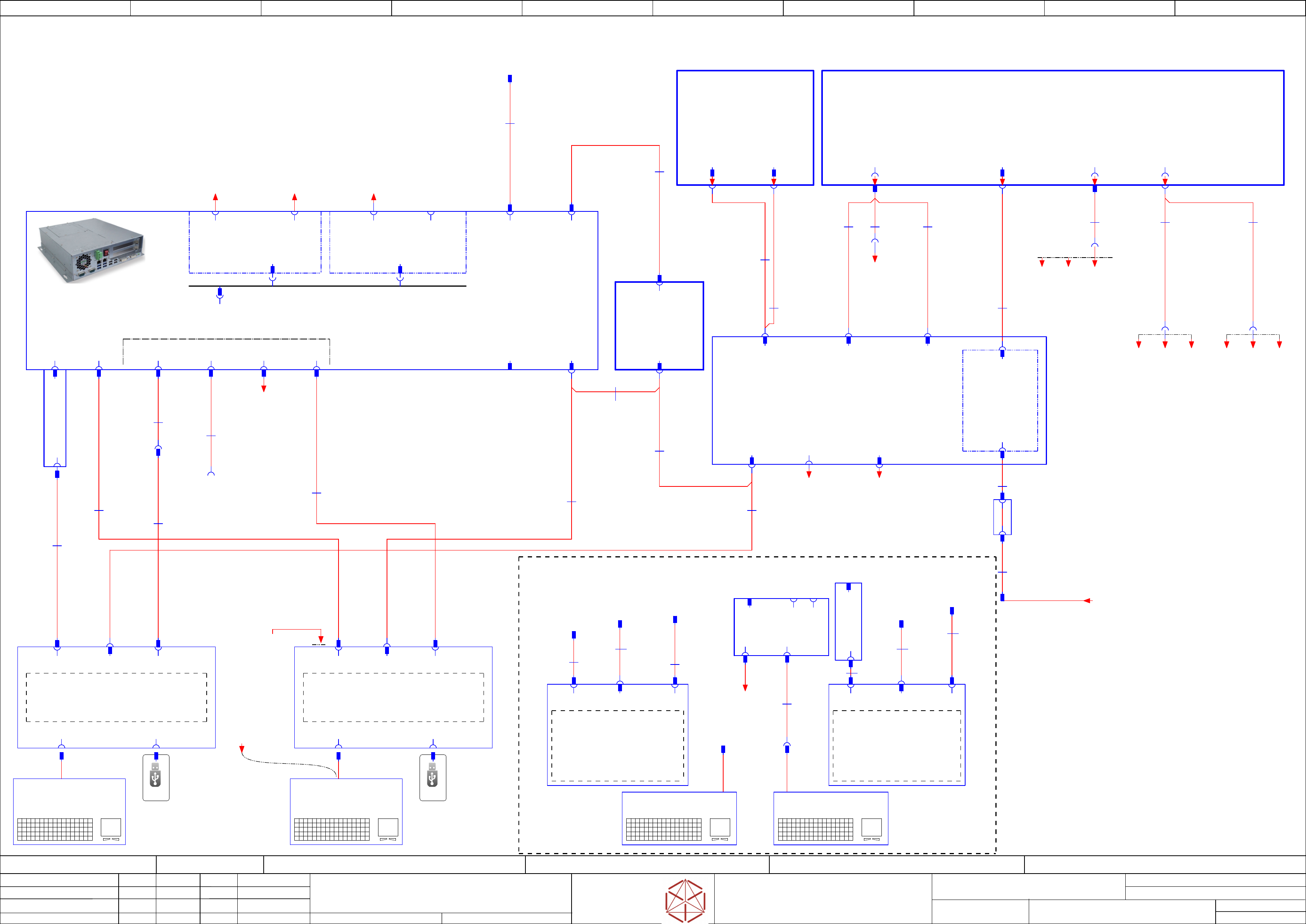
Block_diagram
Wiring base module
supply, Distributor, PC- HMI
Replaced by
Weitergabe sowie Vervielfältigung dieser Unterlage, Verwertung und
Mitteilung des Inhalts nicht gestattet, soweit nicht ausdrücklich zugestanden.
Proprietary Data, company confidential.
All rights reserved
Copying of this document, giving it to others and the use or
communication of the contents thereof, are forbidden without express authority.
Doc. No.
00 01 02 03 04 05 06 07 08 09
Privileged business information.
Do not release
Offenders are liable to payment of damages. All rights are reserved in the
event of the grant or the registration of a utility model or design.
Zuwiederhandlungen verpflichten zu Schadenersatz. Alle Rechte vorbehalten,
insbesondere für den Fall der Patenterteilung oder GM-Eintragung vorbehalten.
Page:
Function: Overview
==OV=SX12_V3+CH/11
drawing number:
03200800-010301LE3
Cable_harness
GmbH & Co KG
ASM
Assembly Systems
Copyright reserved
Ed.
Original
maettig
Date
Date
Modification
Appr
29.04.2020
Name
starting MC-Nr.: 2018/Q3 G. Pingist
Size DIN A2
Sheet
11
/
3
USB-STICK
3.0(2.0)
Service
(Data-handling)
USB-STICK
3.0(2.0)
Service
(Data-handling)
- Option -
- Option -
4x USB 3.0
-KBD1
USB keyboard with touch pad
03059594
==CH+CTRL/58.01
-PC
Control Computer
Control computer BoxPC-427D i3 2xPCIe
03114177
==CH+CTRL/58.00
-PH.MON1
Monitor DV1225-007 12.1 inch multi-touch
03156514
==CH+CTRL/58.00
-qa
==PS002+VAC_P/45.01
-X80
Power
max 4A
100W
-X70
DVI-I
-XVGA1.PC
5 m
VGA Monitor connection
cable
03112234
-W1
-X3.MON1
-X71.PC
5 m
USB cable A-plug -
B-plug
03233152
-W1
-X1
Power
-X3
SVGA
-X5
USB B Plug (IN)
-X5.MON1
5 m
USB cable A-plug -
B-plug
03112236
-W1
-XUSB1.PC
USB
-X4qa
24V Voltage CIN, PC
Monitor-1/2
-X4qa
03200831
-W1.1
03200831
-W1.2
-FD.A1
Fuse and distribution
03104070
==PS002+/44.00
-X71
DisplayPort
4 m
Connection cable
DisplayPort
03233156
-W1
-X60 -X61 -X62
-X3.MON2
-X63.PC
-CIN
CAN Interface CIN
03108598
==CH+CTRL/58.07
-LAN
-LAN.CIN
-POWER
+24V DC
03112243
-W1
Patch cable CAT.5e S-FTP 8x0,14 mm² 1 m
03200831
-W1.4
-X63
-X62.PC
-X2P1
LAN2
03198999
LAN card PCI Express 2x Gigabit LAN
-PC.LAN
*** Optional ***
-X3P2
-X2P1.PC
Patchkabel Cat.5e FTP 8x0,14 mm²
03010478
-W1
-X1
LAN2
to line computer
-X1P1
LAN1
-X1P1.PC
-W1.3
03200831
-X3qa
Power-Supply XB2
Power 24V distributor
-X3qa
PCB Handling
03068128
-W1
-XB4qy
-X79
Conveyor
-X17qa
-X17qa
Vaccum_Pump
** Option **
-XB2qy
-X2qa
Power-Supply XB2
voltages_vision
-X2qa
03068126
-W1.1
-X1pb
03068126
-W1.2
03068126
-W1.3
-X11qa
Power
coplan_sensor
-X11
diagnostic-interface
03119738
-W24
-X11qb
-XB4
Conveyor
-XB2
Power Distributor
& PC 3D-Sensor
-X9qa
distributor unit safety loop
03200834
-W10.2
-X29.CSB
distributor unit safety loop
03200834
-W10.1
-X29
-X30.CSB
-X30
-X9qa
Power-Supply X200
Emergency & Signals
-A2
Safety breaker unit
PCB Pre-/discharge assembly
03108631
==CSB+/46.00
-X5.FD
-X131
FCU2 Power
-X111
FCU1 Power
FCU connection
03109616
-W9.1
FCU connection
03109616
-W9.2
-X5
FCU 1&2
DC 27V
-X14qb
-X0.CAP1
Diagnose buffer module
03119414
-W23
-X1.AD1
-AD1
RJ45 Adapter
03098672
==PS002+/43.06
-X2.AD1
Diagnose buffer module
03112249
-W1
-X14
-XUSB1_2.PC
-X60.PC
0,5 m
USB extension cable
03233565
-W1
-X2
Diagnostic
serial interface
-X2.FD
PCI Riser-extension
-X1.MON1
-PC.GigE
GigE Ethernet Adapter dual-Port
PCI-E I350T2BLK
03115569
-X1
RJ45
GigE 1
-X2
RJ45
GigE 2
-A1(qb)
-X6
USB A plug (OUT)
Service (keyboard)
-KBD-X1
-X7
USB A plug (OUT)
Service
(Data_handling)
-PH.MON2
Monitor DV1225-007 12.1 inch multi-touch
03156514
==CH+CTRL/58.04
-X1
Power
-X3
DisplayPort
-X5
USB B Plug (IN)
-X6
USB A plug (OUT)
Service (keyboard)
-X7
USB A plug (OUT)
Service
(Data_handling)
-X1.MON2
-X5.MON2
USB
-KBD-X1
-KBD2
USB keyboard with touch pad
03059594
==CH+CTRL/58.06
-X4P2
PCI-e(x16) Slot1 PCI-e(x4) Slot2
-KBD1
USB keyboard with touch pad
==CH+CTRL/59.04
-KBD2
USB keyboard with touch pad
==CH+CTRL/59.05
USB
-MON1
Flat Screen SCD1520-TDC
03078913
==CH+CTRL/59.00
-X1
Power
-X3
SVGA
-X5
USB(IN)
USB
-MON2
Flat Screen SCD1520-TDC
03078913
==CH+CTRL/59.05
-X3
SVGA
-X1
Power
-X5
USB(IN)
-X3.MON2
-X5.MON2-X1.MON -X1.MON
03223354
-W1
-X1
03223354
-W1
-X1
03233286
-W1
-X62.PC
-U1
Adapter
VGA-DVI
03195016
-XVGA2.PC
VGA
-X70.PC
DVI
-X61.PC
5 m
USB extension cable
03233431
-W1
-X1.KBD1
-X30
COM1
-XVGA1.PC
03112234
-W1
-X3.MON1
-X5.MON1
03112236
-W1
-XUSB1.PC
-X1.KBD2
-X1
-X63.PC
03233152
-W1
-X71.PC
-U2
Adapter
VGA-DP
03191848
-XVGA2.PC
-XVGA2.PC
03233613
-W1
-U3
USB 3.0 hub
03192485
-XUSB1
-XUSB2
-XUSB3
-XUSB4
-XUSB2
-X62.PC
-C_3D_VGA
+3D_Coplan/38.05
** Optional **
from Computer 3D sensor
-USB_Code_Reader.1
** Optional **
==CH+CTRL/58.04
LAN.3
** Optional **
Code-reader Lector260
or
3D_coplanarity_sensor
+3D_Coplan/38.04
+CR_Lector620/40.05
==CO+-POWER
-CO_Power
+PS002/10.05
-POWER.DI
+PS002/10.02
==CO+-POWER.r
single-Conveyor/right
+CO001/32.11
==CO+-POWER.l
single-Conveyor/left
+CO002/34.11
==COTi60+Loc2-POWER_COTi.60
+COTi60/18.01
==COTi60+Loc1-POWER_COTi.60
+COTi60/20.01
+-POWER_PC_2
** Optional **
Computer 3D sensor
+3D_Coplan/38.06
==+Loc1-POWER_MT
alternative Manual_table1_MT60
==+Loc2-POWER_MT
alternative Manual_table2_MT60
==COTi30+Loc1-POWER_COTi.30
+COTi30/15.01
==COTi30+Loc2-POWER_COTi.30
+COTi30/15.01
+-C_3D_Power
+3D_Coplan/38.08
** Optional **
3D_coplanarity_sensor
Control_VAC_Punp
-DIAG.S
+PS002/10.05
-Safety_Sig.DI
+PS002/10.06
-Safety_Loop.DI
+PS002/10.07
-POWER.COTi
+PS002/10.02
==GA=+-VBI.1
Vision Base Interface-1
+GA/24.09
==GA=+-VBI.2
Vision Base Interface-2
+GA/25.09
-C_3D.USB
SX-Series SX1 and SX2 V3
+3D_Coplan/38.04
Diagnostic.CAP1 USE 100 or 1000 Base-T
+PS002/10.01
-USB_Code_Reader.2
** Optional Code-Reader **
==CH+CTRL/59.06
electric_schematic_SX12_V3
90013315-010101LE3
Replaced by
Block_diagram
Wiring-base-module
Distributor
Replaced by
Weitergabe sowie Vervielfältigung dieser Unterlage, Verwertung und
Mitteilung des Inhalts nicht gestattet, soweit nicht ausdrücklich zugestanden.
Proprietary Data, company confidential.
All rights reserved
Copying of this document, giving it to others and the use or
communication of the contents thereof, are forbidden without express authority.
Doc. No.
00 01 02 03 04 05 06 07 08 09
Privileged business information.
Do not release
Offenders are liable to payment of damages. All rights are reserved in the
event of the grant or the registration of a utility model or design.
Zuwiederhandlungen verpflichten zu Schadenersatz. Alle Rechte vorbehalten,
insbesondere für den Fall der Patenterteilung oder GM-Eintragung vorbehalten.
Page:
Function: Overview
==OV=SX12_V3+CH/12
drawing number:
03200800-010301LE3
Cable_harness
GmbH & Co KG
ASM
Assembly Systems
Copyright reserved
Ed.
Original
maettig
Date
Date
Modification
Appr
29.04.2020
Name
starting MC-Nr.: 2018/Q3 G. Pingist
Size DIN A2
Sheet
12
/
3
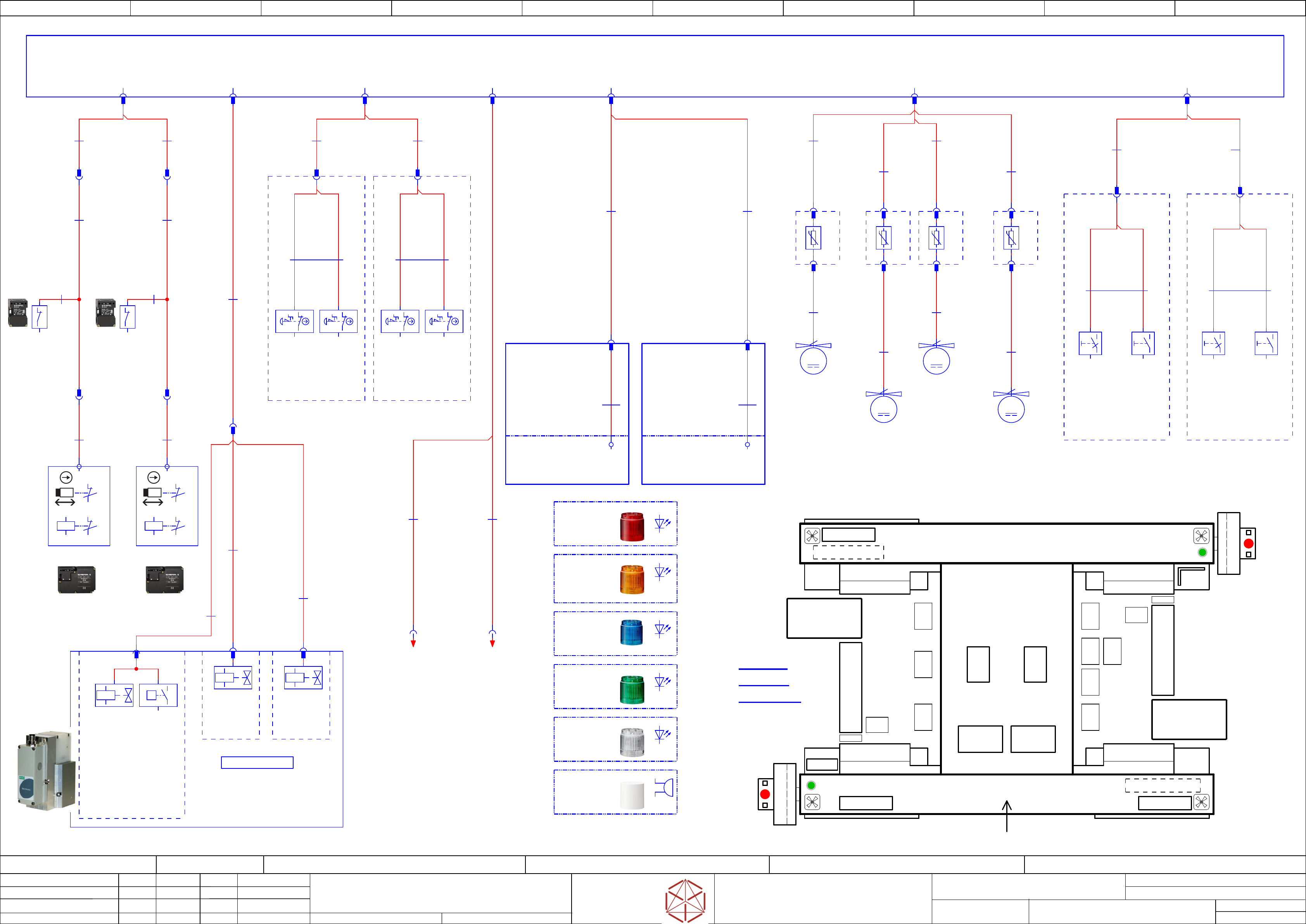
-PF6.1(2)
LED unit LR5-E-RZ
50mm red clear
03162664
-PF4.1(2)
LED unit LR5-E-BZ
50mm blue clear
03162668
LP-Transfer
Siplace
electric
overview
Sector-3
Sector-4
Sector-1
MGCU2
PC
MGCU1
Power-supply
Pneumatic-unit
SMEMA interface-terminal
PC 3D-sensor (Option)
Hood-2
Hood-1
WPC2
WPC1
FCU2
FCU1
PPW3IC2PPW4
PPW2IC1PPW1 FC1
Coplan
Tape-
Cutter1
Tape-
Cutter1
PCB-Control
Lane-1
PCB-Control
Lane-2
HCU
3/4
HCU
1/2
CIN(Can)
Distri.
unit
Fault ind. Lamp
Fault ind. LampTrailing-interface-2
Trailing-
interface-1
Start
Emerg. Stop
Stop
Monitor
Keyboard
Start
Emerg. Stop
Stop
Monitor
Keyboard
Sector-2
2
-S1
2
-S1
3
3
-S1
Hood1
Solenoid interlock SX
-K1
3
3
-S2
Hood2
Solenoid interlock SX
-K1
Safety switch for
buffer monitoring-1
Safety switch for
buffer monitoring-2
-X91
-Y_PV1
Proportional_valve_1
Sentronic-LP Serie 617
Proportional valve Sentronic-LP
03152704
==CH+DI/55.00
-Y_PV1
regulated-air
4,74bar
-S1(PV1)
pressure_sensor
switches at 4,5bar
P
-X89
-Y1
Main_pressure_valve
Valve-5/2 G1/8
03062277
==CH+DI/55.01
-X90
-Y2
Safety_valve
Valve-5/2 G1/4
00344974
==CH+DI/55.02
==FLUID+-U1
Pneumatic Group 1
03056289-
==CH+DI/55.00
-M1
M
2
-M3
M
2
-M2
M
2
-M4
M
2
Single core
8x0,75
03112121
-W1.1
Cable: Extension Hood 1 and 2
-X6qa
-X6qa
Hood-1/Hood-2
-X10qa
Fault_indicator_lamp
Pneumatic
Main_System
03052264
-W1
-X7qa
-X60
-X60
-X91
-X89 -X90
Pneumatic System
Proportional valve 1
03106361
-W1.3
-X5qa
Gantry voltages VLT33
-X5qa
Power stationary
camera
03200832
-W1.1
Power stationary
camera
03200832
-W1.2
-X4am-X4bm
-X51
-X51.1 -X61.1
-X61
Single core
8x0,75
03112121
-W1.2
Cable: Extension Hood 1 and 2
-X51.2
-X51
UNITRONIC® LiYY A
2x0,75
03112126
-1W1.2
Safety switch buffer monitoring1_2
Single core
7x0,75
03112126
-2W1.1
Safety switch buffer monitoring1_2
-S1
03078745
Single core
7x0,75
03112126
-1W1.1
Safety switch buffer monitoring1_2
UNITRONIC® LiYY A
8x0,34
03112130
-1W1
Solenoid interlock Hood1_2
-X61.2
-X61
-S2
03078745
UNITRONIC® LiYY A
2x0,75
03112126
-2W1.2
Safety switch buffer monitoring1_2
UNITRONIC® LiYY A
8x0,34
03112130
-2W1
Solenoid interlock Hood1_2
-X7qa
Pneumatic
Main_System
Emergency controls
03052263
-W1.1
-X8qa
-X52
-X52
-X8qa
Conntrol_elements
Emergency_Stop_Button
Emergency controls
03052263
-W1.2
-X62
-X62
-S1 -S2 -S1 -S2
==CH+DI/55.02
03173672
Emergency stop right
+CTRL_EMG_R
==CH+DI/55.03
03173672
Emergency stop left
+CTRL_EMG_L
CTRL_R
emergency
stop
03173672
-W1
CTRL_L
emergency
stop
03173672
-W1
-X19qa
HOOD_fans &
Monitoring
-X19qa
03071336
-W1.1
03094598
-4W1
03071336
-W1.2
03094598
-1W1
03071336
-W1.3
03094598
-3W1
03071336
-W1.4
03094598
-2W1
Extension control
Element start/stop
03052261
-W1.1
-X20qa
-X53
-X53
CTRL right
-X20qa
Control_elements_left/right
Monitor-1/2
Extension control
Element start/stop
03052261
-W1.2
-X63
-X63
CTRL left
03173673
-W1
-S3
Pneumatic System
Safety valve
03106361
-W1.2
Pneumatic System
Main pressure valve
03106361
-W1.1
-X1
NTC Thermistor 10R
-Inrush.Fan2
-X1km -X1fm -X1hm -X1gm
-X1km -X1fm -X1hm -X1gm
-X2
-X1
NTC Thermistor 10R
-Inrush.Fan3
-X2
-X1
NTC Thermistor 10R
-X2
-Inrush.Fan4
-X1
NTC Thermistor 10R
-Inrush.Fan1
-X2
==CH+DI/57.07
03173673
Controls start/stop on
the right
+CTRL_R
==CH+DI/57.08
03173673
Controls start/stop on
the left
+CTRL_L
03173673
-W1
-S3
-PJ1.1(2)
Buzzer unit LR5-BW
50mm
03162667
Buzzer
white
-PF2.1(2)
LED unit LR5-E-CZ
50mm white clear
03162666
green
-PF3.1(2)
LED unit LR5-E-GZ
50mm green clear
03162663
yellow
-PF5.1(2)
LED unit LR5-E-YZ
50mm yellow clear
03162665
red
-qa
==PS002+VAC_P/45.01
-X1.FIL
-UB1
(Basis module
and connection cable)
==CH+DI/55.04
Signal tower 1
-UB1.1
Body unit LR5-02WTNW
50mm 24VDC
03162662
8x0,23
03209094
-W1
-X10qa
-X1.FIL1 -X1.FIL2
-UB2
(Basis module
and connection cable)
==CH+DI/55.06
Signal tower 2
-UB2.1
Body unit LR5-02WTNW
50mm 24VDC
03162662
8x0,23
03209094
-W1
-X1.FIL
blue
Fault indicator lamp
03200833
-W1.1
Fault indicator lamp
03200833
-W1.2
==stCAM=+Loc1-Power
+stCAM/14.03
==stCAM=+Loc2-Power
+stCAM/14.08
electric_schematic_SX12_V3
90013315-010101LE3
Replaced by
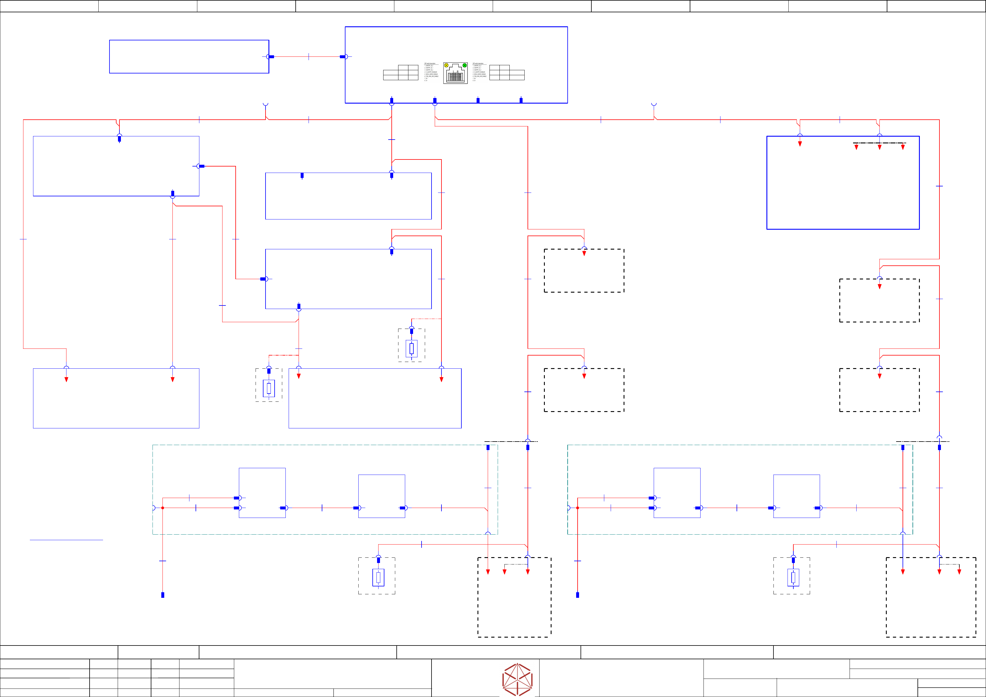
Block_diagram CAN-BUS 1 & 2
Replaced by
Weitergabe sowie Vervielfältigung dieser Unterlage, Verwertung und
Mitteilung des Inhalts nicht gestattet, soweit nicht ausdrücklich zugestanden.
Proprietary Data, company confidential.
All rights reserved
Copying of this document, giving it to others and the use or
communication of the contents thereof, are forbidden without express authority.
Doc. No.
00 01 02 03 04 05 06 07 08 09
Privileged business information.
Do not release
Offenders are liable to payment of damages. All rights are reserved in the
event of the grant or the registration of a utility model or design.
Zuwiederhandlungen verpflichten zu Schadenersatz. Alle Rechte vorbehalten,
insbesondere für den Fall der Patenterteilung oder GM-Eintragung vorbehalten.
Page:
Function: Overview
==OV=SX12_V3+CH/13
drawing number:
03200800-010301LE3
Cable_harness CAN
GmbH & Co KG
ASM
Assembly Systems
Copyright reserved
Ed.
Original
maettig
Date
Date
Modification
Appr
29.04.2020
Name
starting MC-Nr.: 2018/Q3 G. Pingist
Size DIN A2
Sheet
13
/
3
CAN-BUS-1
CAN-BUS-2
not used
Optional-connection
CAN2-WPT1
Optional-connection
CAN2-WPT2
CAN bus wiring
wire no. wiring SUB-D pin
1
2
3
4
5
6
7
8
9
free
GND
CAN_L
CAN_H
GND
free
free
free
free
1
6
2
7
3
8
4
9
5
Note:
CAN Terminating Resistor (120 Ohm)
Set the DIP-switches to
ON-position (= terminated).
1 2
ON ON
OFF OFF
X-Ser S
SX1/2
3 4
ON ON
OFF OFF
X-Ser S
SX1/2
LAN120Ohm 120Ohm
120R
TR2
03027646
one_Gantry_version only
Terminating
Resistor
120R
TR2
03027646
one_Gantry_version only
Terminating
Resistor
-MGCU1
Position controller gantry axis MGCU-3
03103477
Gantry 1
==CH+GA/62.00
-X74Usc
-X1Usc
GCAN
-ao
CAN2_in_out
==CH+CAN/61.03
Optional =
single-Conveyor-right
single-Conveyor/left
-PC
Control computer BoxPC-427D i3 2xPCIe
03114177
==CH+CTRL/58.00
-X2 -X1
MCAN-BUS 1
03112114
-W1.4
MCAN-BUS 2
03099372
-W2.1
-MGCU2
Position controller gantry axis MGCU-3
03103477
Gantry 2
assembly two_Gantry_version only
==CH+GA/64.00
-X1_q
-aa
Trailing-Interface SX1/2 (GigE)
03215039
MCAN-BUS 1
03112114
-W1.3
MCAN-BUS 1
03112114
-W1.2
-CAN2.CIN-CAN1.CIN-CAN1.SERVICE
MCAN 1
-X1qb
-X2pn2
MCAN 2 Service
-X1Osc
-X17aa
-X1Ouc
-X1Usc
-X115
-X1_p
MCAN-BUS 1
03112114
-W1.1
MCAN-BUS 1
03112114
-W1.5
-ca
Trailing-Interface SX1/2 (GigE)
03215039
two_Gantry_version only
-X17ca
MCAN-BUS 1
03112114
-W1.6
MCAN-BUS 2
03099372
-W2.3
-X10am
Location-1
Stationary IC-cameras
MCAN-BUS 2
03099372
-W2.5
MCAN-BUS 2
03099372
-W2.6
-X7ap -X7ao
MCAN-BUS 2
03099372
-W2.2
MCAN-BUS 2
03099372
-W2.4
-X10bm
Location-2
Stationary IC-cameras
MCAN-BUS 2
03099372
-W2.8
MCAN-BUS 2
03099372
-W2.9
MCAN-BUS 2
03099372
-W2.7
-X135
-X18aa
-X1Uuc
GCAN
-X1Uuc
-X18ca
-X115
-X31p
MCAN-BUS 2
03060471
-W2.11
-X116
-W2.12
MCAN-BUS 2
03060471
120R
/13.08
-A
Terminating
Resistor
03027646
120R
/13.03
-A
Terminating
Resistor
03027646
-X1_5
-X3_p
03072093
-W1.2
-CAN_SW1
Can-switch
==COTi30+Loc1_2/72.05
-X74Uuc
-X74Uuc
MGCU1 - MGCU2 bus
-X2_q
-W1.1
03072093
==COTi30+CAN-CAN_WPC1
Machine-Can-Bus-2 extention for WPC1
==COTi30+CAN/68.00
-X1 -X1.1
-CAN_TERM1
Ca-Bus-terminator
==COTi30+Loc1_2/72.03
-X2
-W1
03072098
-X21p
-X2
-W3
03072097
-X200.(WPC1)
-X135
-X32p
MCAN-BUS 2
03060471
-W2.21
-X136
-W2.22
MCAN-BUS 2
03060471
03055207
-W1
-X74Usc
MGCU1 - MGCU2 bus
GCAN-BUS
03112107
-W3.4
GCAN-BUS
03112107
-W3.3
GCAN-BUS
03112107
-W3.1
-X1qs.(WPC1)
-X14pa Distributor
Safety + Signaling
Cable
Interface WPC
Safety + Signaling
03072097
-W1
-X3-X3
-W2
03072097
-X1_q -X1_p
-X125
-X32p
03072093
-W1.2
-CAN_SW2
Can-switch
==COTi30+CAN/68.05
-X2_q
-W1.1
03072093
==COTi30+CAN-CAN_WPC2
Machine-Can-Bus-2 extention for WPC2
==COTi30+CAN/68.05
-X1 -X1.1
-CAN_TERM2
Ca-Bus-terminator
==COTi30+CAN/68.05
-X2
-W1
03072098
-X21p
-X2
-W3
03072097
-X200.(WPC2)
-X3-X3
-W2
03072097
-X1qt.(WPC2)
-X16pa Distributor
Safety + Signaling
Cable
Interface WPC
Safety + Signaling
03072097
-W1
==CH+CTRL/58.07
03108598
CAN Interface CIN
-CIN
-LAN
-LAN.CIN
-CAN4-CAN1 -CAN2 -CAN3
-X1P1
LAN1
-X1.PC
-W1
03112243
Patch cable CAT.5e S-FTP
-X1Osc
MCAN 1
-X1Ouc
MCAN 1
-X10cm
Location-2
Stationary FC-cameras
-X10dm
Location-1
Stationary FC-cameras
==CO+-CAN.Lane2
dual-Conveyor
==CO+-CAN.Lane1
+CO003/36.12
dual-Conveyor
==COTi60+Loc1-MCAN.1
+COTi60/18.02
FCU COTi_Loc1
==GA1+-MCAN
+GA/24.08
End-Termination
==GA1+-GCAN
+GA/24.07
End-Termination
==CO+-CAN.CO_r
+CO001/32.12
single-Conveyor/right
==CO+-CAN.CO_l
+CO002/34.12
single-Conveyor/left
==GA2+-MCAN
+GA/25.08
End-Termination
==GA2+-GCAN
+GA/25.07
End-Termination
==IC=+Loc1-CAN.2
+stCAM/14.03
==IC=+Loc2-CAN.2
+stCAM/14.08
==COTi60+Loc2-MCAN.2
+COTi60/20.02
FCU COTi_Loc2
==MT60+Loc1-MCAN.1
alternative MT60
==MT60+Loc2-MCAN.2
alternative MT60
==COTi30+Loc2-MCAN.2
+COTi30/15.02
==COTi30+Loc1-MCAN.1
+COTi30/15.02
==FC=+Loc2-CAN.2
+stCAM/14.06
==FC=+Loc1-CAN.1
+stCAM/14.02