ASM贴片机SX2机型电路图.pdf - 第46页
electric_schematic_SX12_V3 90013315-010101LE3 Replaced by Mains input Replaced by Weitergabe sowie Vervielfältigung dieser Unterlage, Verwertung und Mitteilung des Inhalts nicht gestattet, soweit nicht ausdrücklich zuges…
electric_schematic_SX12_V3
90013315-010101LE3
Replaced by
wiring protection earth
Replaced by
Weitergabe sowie Vervielfältigung dieser Unterlage, Verwertung und
Mitteilung des Inhalts nicht gestattet, soweit nicht ausdrücklich zugestanden.
Proprietary Data, company confidential.
All rights reserved
Copying of this document, giving it to others and the use or
communication of the contents thereof, are forbidden without express authority.
Doc. No.
0 1 2 3 4 5 6 7 8 9
Privileged business information.
Do not release
Offenders are liable to payment of damages. All rights are reserved in the
event of the grant or the registration of a utility model or design.
Zuwiederhandlungen verpflichten zu Schadenersatz. Alle Rechte vorbehalten,
insbesondere für den Fall der Patenterteilung oder GM-Eintragung vorbehalten.
Page:
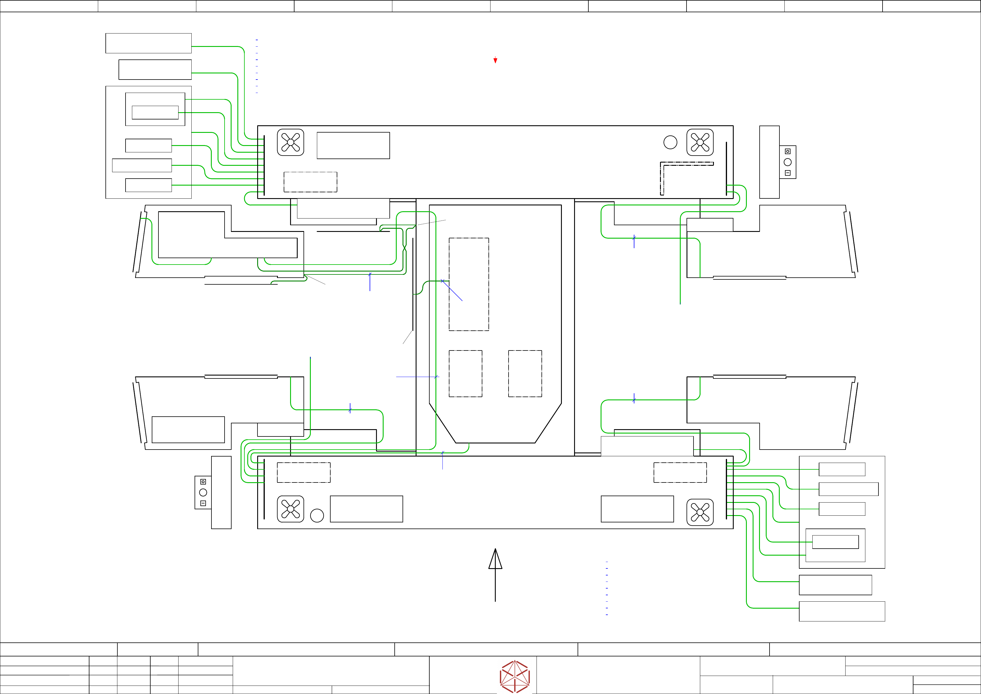
Function: Overview
==OV=SX12_V3+PE/41
drawing number:
03055284-030401LE3
protection earth
GmbH & Co KG
ASM
Assembly Systems
Copyright reserved
Ed.
Original
schnedlitz
Date
Date
Modification
Appr
30.04.2020
Name
starting MC-Nr.: 2018/Q3 G. Pingist
Size DIN A2
Sheet
41
/
1
Side part M5
M5
Door
Side partM5
M5
M5
Door
Side partM5
M5
M5
Door
Side part M5
M5
M5
Door
14
Side cover cpl. M5 1 m 03055212
MGCU holder M5 1 m 03055212
Trailing interface holder M5 0,5 m 03055213
Trailing interface 2 M5 0,5 m 03055213
Support corner left M5 0,5 m 03055213
Side part left M5 0,5 m 03055213
Door left M5 1 m 03055212
Side part right M5 0,5 m 03055213
Support plate trailing cable M5 0,5 m 03055213
Start
Stop
Emergency stop
Monitor, keyboard 2
Start
Stop
Emergency stop
Monitor, keyboard 1
Signal tower
Distributor
unit
M6
M6
M6
M6
Signal
tower
Hood switch 1
SMEMA interface
Hood switch 2
Support plate
trailing cable
M5
Plate cable harness
Support plate
trailing cable
M5
M5
Pneumatic unit
PE terminal block
Cover left
03055218
2,6 m
03076529
(Part of power supply)
M5 external
M6 (Base module)
Cover trafo unit
M5
Sector 1
Sector 2
Sector 4
Sector 3
Side cover cpl. M5 1 m 03055212
MGCU holder M5 1 m 03055212
Trailing interface holder M5 0,5 m 03055213
Trailing interface 2 M5 0,5 m 03055213
Support corner left M5 0,5 m 03055213
Side part left M5 0,5 m 03055213
Door left M5 1 m 03055212
Side part right M5 0,5 m 03055213
Support plate trailing cable M5 0,5 m 03055213
2,6 m
03055218
2,6 m
03055218
Side cover cpl.
M5
Support
corner left
M5
Side part right
M5
Door left
M5
Side part left
M5
Trailing int. holder
M5
Trailing
interface 2
M5
MGCU holder
M5
MGCU 2
COT / WPC insert
03055212
1 m
Trailing
interface 2
Side cover cpl.
M5
Support
corner left
M5
Side part right
M5
Door left
M5
Side part left
M5
Trailing int. holder
M5
Trailing
interface 1
M5
MGCU holder
M5
MGCU 1
Trailing
interface 1
Control computer
1 m
03055212
COT / WPC insert
PC 3D sensor
(option)
PCB
Control
2
PCB
Control
1
Trafo
unit
03052593
1,5 m
Switching
unit
4 m
03055205
CAN Interface
CINX
===+-MC_PE
wiring general protection earth
+PS002/10.0
03076519
(Part of
trafo unit)
electric_schematic_SX12_V3
90013315-010101LE3
Replaced by
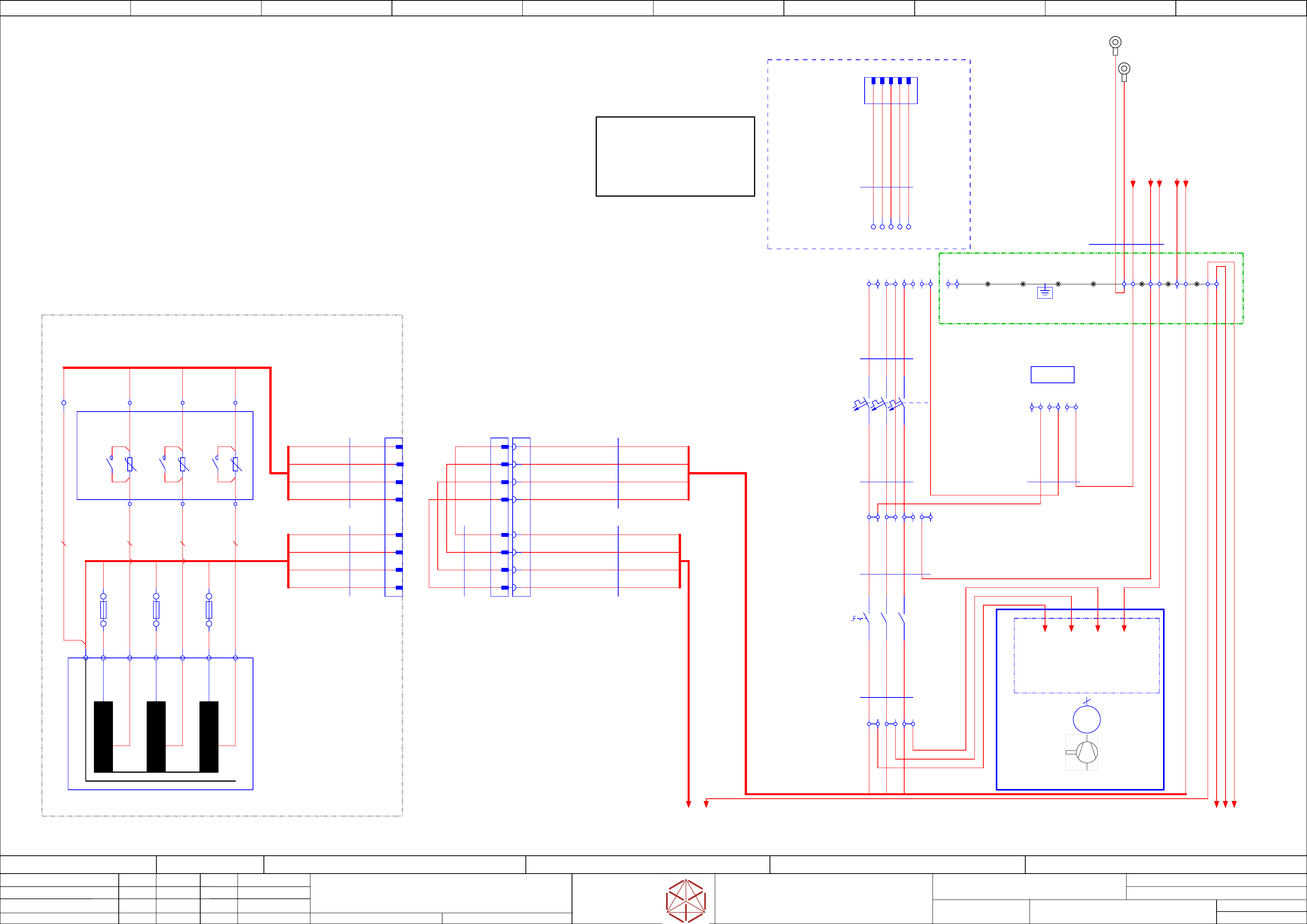
Mains input
Replaced by
Weitergabe sowie Vervielfältigung dieser Unterlage, Verwertung und
Mitteilung des Inhalts nicht gestattet, soweit nicht ausdrücklich zugestanden.
Proprietary Data, company confidential.
All rights reserved
Copying of this document, giving it to others and the use or
communication of the contents thereof, are forbidden without express authority.
Doc. No.
0 1 2 3 4 5 6 7 8 9
Privileged business information.
Do not release
Offenders are liable to payment of damages. All rights are reserved in the
event of the grant or the registration of a utility model or design.
Zuwiederhandlungen verpflichten zu Schadenersatz. Alle Rechte vorbehalten,
insbesondere für den Fall der Patenterteilung oder GM-Eintragung vorbehalten.
Page:
Function: Power Supply SX12 V3, switched mode
==PS002=SX12_V3/42
drawing number:
03233467-010101LE3
GmbH & Co KG
ASM
Assembly Systems
Copyright reserved
Ed.
Original
maettig
Date
Date
Modification
Appr
04.05.2020
Name
starting MC-Nr.: 2018/Q3 G. Pingist
Size DIN A2
Sheet
42
/
3
Q2-L1
Q2-L2
Q2-L3
Q2-PE
Q2-L3
Q2-L2
Q2-PE
Q2-L1
CORE
Q2-L1'
Q2-L2'
Q2-L3'
T1-L1'
T1-L2'
Q2-PE'
T1-L3'
Q2-L1'
Q2-PE'
Q2-L2'
Q2-L3'
T1-L1'
T1-L2'
T1-L3'
T1-PE'
T1-PE'
Mains testing
terminals
Mains supply (TN-C, TN-S, TN-C-S)
3 x 380 V AC .... 3 x 415 V AC +/- 10%
Low Voltage Option
3 x 200 V AC .... 3 x 240 V AC +/- 10%
50 / 60 Hz 2.1 .. 2.4 kVA
T1-PE
T1-L1
T1-L2
T1-L3
-X1.FLR
Cable lug
Floor
M5
1
2
3
4
5
-X2
Mains Connection
CEEE05S
L1/L2/L3/N/PE
3
L3
4
N
2
L2
-X94
1
L1
X1
3
MGP
X1
2
MGP
-X101
1
2
3
4
5
6
7
8
1000 mm
4G2,5
ÖLFLEX® 191 UL/CSA
03110977-02
-W2.1
1
2
3
GNYE
-S1
25 A
Main power switch
EAT.P1-25/SVB-MCS
1
2
3
4
5
6
3
L3
2
L2
-X96
X96-L1
Interruptable Power distribution
*** Optional ***
If complete machine
has to be switched off
using only one control
1
L1
-MGP-PE
Main_ground_point
ÖLFLEX® 191 UL/CSA
4G2,5
1100 mm
03110977 -02
-W2.2
1
2
3
GNYE
-X101BR
Supply Bridge (Plug)
1
2
3
4
5
6
7
8
5 5
Single-wire
4x2,5
100 mm
03110977 -02
-W3
1
2
3
GNYE
-F1
16 A C
Line protection
EAT.FAZ-C16/3-NA
1
2
3
4
5
6
X1
1
MGP
3+PE
3~
M
-qr
3
L3
2
L2
-X95
1
L1
#03232247
retrofitkit_vacuumpump_IE3_SX12_V3
-X1.CVR
Cable lug
Front door
M5
3x4,0
single core
03124591 -02
-W25.1
4,0 OG
4,0 OG
4,0 OG
3x2,5
single core
03124591 -02
-W25.2
3x2,5
single core
03124591 -02
-W25.3
2,5 BK
2,5 BK
2,5 BK
3x2,5
single core
03124591 -02
-W25.4
2,5 GNYE
2,5 BU
2,5 OG
5x2,5
single core
03124591 -02
-W25.5
2,5 GNYE
2,5 GNYE
2,5 GNYE
2,5 GNYE
2,5 GNYE
2,5 OG
2,5 OG
2,5 OG
4x2,5
single core
03124591 -02
-W25.2
2,5 OG
2,5 OG
2,5 OG
X95
4
MGP
U`
U
V`
V
W`
W
1U1; ;415 V
1U2208 V
1V1415 V
1V2; 208 V
1W1; 415 V
1W2; 208 V
-T1
3P208V/400V/5,05A
-A100
Inrush
current limiter
-OPT_LowVoltage
Low Voltage adaption kit (Option)
3P208V/400V/5,05A
03107593
PEPE
-R
-K1
1
2
3
4
5
6
2,5 BK
2,5 BK
2,5 BK
1U 2 3
PE
200 V input
1U 2 3
2,5 GNYE
2U2U
-F1
Fuse 6,3 A T
400 V output
2V2V
-F2
Fuse 6,3 A T
2W2W
-F3
Fuse 6,3 A T
-X101.TR
Low Voltage
Option
Converter
Connection
- Optional-Connection -
1
2
3
4
6
7
8
5
9
ÖLFLEX® 191 UL/CSA
4G2,5
1100 mm
03121277 -02
-W1.2
1
2
3
GNYE
1100 mm
4G2,5
ÖLFLEX® 191 UL/CSA
03121277-02
-W1.1
1
2
3
GNYE
==Intern
Cable mains connection
OPTIONAL
6000 mm
5G4,0
ÖLFLEX® 191
00335210 -02
-W1
BK1
BK2
BN
GNYE
BU
L2 L3 N PEL1
-X94
-MGP-PE
PE DIN-Rail
2,5 GNYE
3
PE
2
N
-X98
1
L
WAGO in a row:
- 2004-1401(GY)
- 2004-1404(BU)
- 2004-1407(GNYE)
- 2004-1492 (End_plate OG)
X94
5
MGP
X301
4
MGP
PE_CAP
/43.1
PE_CSB.A2
==PS+-VP_PE
+VAC_P/45.6
==PS+-VP_L3
+VAC_P/45.5
==PS+-VP_L2
+VAC_P/45.5
==PS+-VP_L1
+VAC_P/45.5
PE_FD.A1
/44.4
PE_MGCU1
==CH+CSB/53.1
PE_MGCU2
==CH+CSB/53.2
PS2-PE
/43.2
PS3-PE
/43.2
PS1-PE
/43.2
T1-PE
/43.2
-Mains-Sub
/43.3
electric_schematic_SX12_V3
90013315-010101LE3
Replaced by
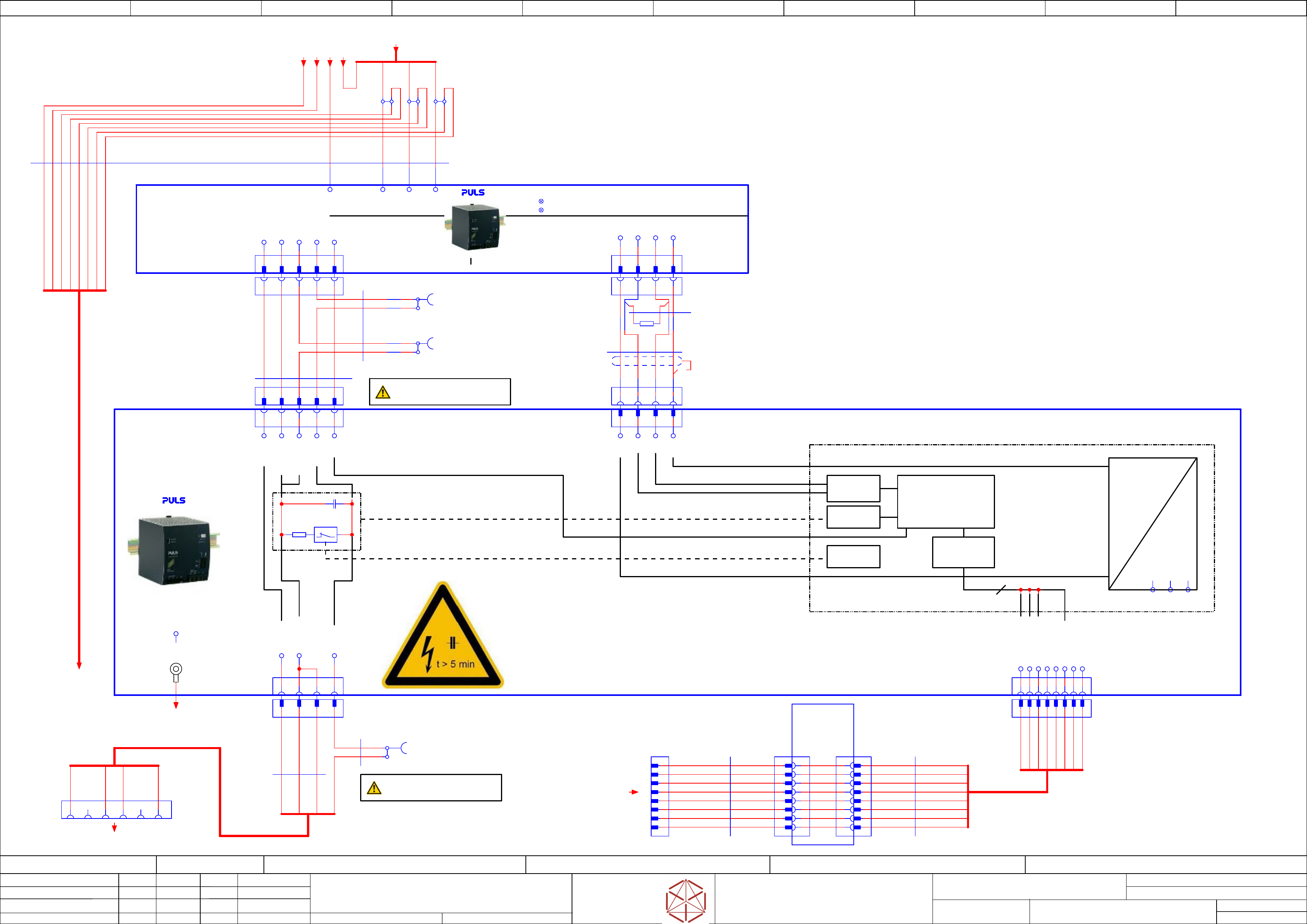
DC 300 V
Replaced by
Weitergabe sowie Vervielfältigung dieser Unterlage, Verwertung und
Mitteilung des Inhalts nicht gestattet, soweit nicht ausdrücklich zugestanden.
Proprietary Data, company confidential.
All rights reserved
Copying of this document, giving it to others and the use or
communication of the contents thereof, are forbidden without express authority.
Doc. No.
0 1 2 3 4 5 6 7 8 9
Privileged business information.
Do not release
Offenders are liable to payment of damages. All rights are reserved in the
event of the grant or the registration of a utility model or design.
Zuwiederhandlungen verpflichten zu Schadenersatz. Alle Rechte vorbehalten,
insbesondere für den Fall der Patenterteilung oder GM-Eintragung vorbehalten.
Page:
Function: Power Supply SX12 V3, switched mode
==PS002=SX12_V3/43
drawing number:
03233467-010101LE3
Power_supply SMPS
GmbH & Co KG
ASM
Assembly Systems
Copyright reserved
Ed.
Original
maettig
Date
Date
Modification
Appr
04.05.2020
Name
starting MC-Nr.: 2018/Q3 G. Pingist
Size DIN A2
Sheet
43
/
3
P_160
P_GND_2
P_GND_1
Discharge
Control
Diagnostic
Master
24V
5 V
Bus Master +
Controller -->
discharge logic
CAP value detection
I/O
ADC:
U, I
RS485
driver
T1-L2
T1-L1
PS2-L1
PS3-L1
PS3-L2
PS2-L3
PS3-PE
Overload
DC ok
GND
GND
RS485
driver
Remark:
No shielded connector at
diagnostic master
Shield is connected to GND
at IOCU
PS2-L2
T1-PE
T1-L3
PS3-L3
PS2-PE
-X1
Power DC-Out
160V/300V
1 2 3 4 5
-X1.CAP1
Phoenix Mini Combicon
QT40 Diagnostic
1234
-X2
Diagnostic Interface
1 2 3 4
-X2
DC-Power out
160V/300V
1 2 3 4
Voltage testing point
Use for testing purpose only!
Voltage testing point
Use for testing purpose only!
1 2 3 4 5 6 87
RJ45
Diagnostic
Master
-X0
GND
RS485_OUT_NINV
RS485_OUT_INV
+24V
RS485_IN_NINV
RS485_IN_INV
+24V
GND
-X0.CAP1
RJ45
Diagnostic Master
1 2 3 4 5 6 7 8
RS485_IN_NINV
GND 1
+24V 2
RS485_IN_INV
GND 2
+24V 1
RS485_OUT_NINV
RS485_OUT_INV
4
-X2
1
2
3
4
5
6
7
8
-X1
1
2
3
4
5
6
7
8
-X2
1
2
3
4
5
6
7
8
RJ45
-X1
1
2
3
4
5
6
7
8
+24V 2
RS485_OUT_NINV
RS485_IN_INV
GND 1
RS485_IN_NINV
GND 2
RS485_OUT_INV
+24V 1
P_300
P_300
P_GND_2
P_160
P_GND_1
-X2.PS1
Diagnostic
1 2 3 4
-X1.PS1
Power
1 2 3 4 5
-X3.CAP1
Power
1 2 3 4 5
1 2 3 4 5
-X1
Diagnostic 1
1234
-X2.CAP1
DC-Power out
1 2 3 4
-PS1
Power Supply 3AC 380-480V
Uout = 300 V DC / 160 V DC
PULS.QT40-999-70
03103087
PE L1 L2 L3
+5 V
D+
PWR_GND
+ 160 V
+300V
D+
D- D-
GND
+5 V
GND
40 mF
-C1
+
Discharge
internal CAP
-R3
-X1:PE
ON
PWR GND
+160 V
+300 V
2 3
+24V
+24V
GND
-X3
DC-IN
160V/300V
PWR GND
-CAP1
DC 300/150
Capcitor Bank
40 mF
PULS.PCS417.381
03103081
480 mm
3x1,5
Single core
03110978-03
-W3.1
500 mm
2x2x0,23
UNITRONIC® LiYCY (TP) A
03110979-02
-W4.1
Use twisted pair cables!
500 mm
5x4
Single Wire
03110981-02
-W5.1
-X302
1
BK BK BK
BK BK BK
#03110979-R1
Termination Resistor
-X303
Service Testing point
DC300 PS1/QT40
WAGO.2007-8801
03114296
1
BK
BK
4x1,5
Single core
-X304
TP2 Service Testing point
DC300 PCS417
WAGO.2007-8801
03114296
1
2x4,0
Single wire
BK
BK
WH GN YE BN
SH
Single wire connections
#03121661-W11.1
2,5 GNYE
2,5 GNYE
2,5
GNYE
2,5
BK
2,5
BK
2,5
BK
-AD1
RJ45 Adapter
EFB.37508.1V2
03098672
1 m
Crossover Cable
03119414
-W23
USE 100 or 1000 Base-T
crossover line ONLY
crossed = Pin 1-3, 2-6
WH-OG
OG
WH-GN
BU
WH-BU
GN
WH-BN
BN
-X14qb
1
2
3
4
5
6
7
8
3,44 m
Patchkabel Cat.5e S-FTP
03112249
-W1
WH-OG
OG
WH-GN
BU
WH-BU
GN
WH-BN
BN
-X305
Service Testing point
DC300 PS1/QT40
WAGO.2007-8801
03114296
1
GND
BK
BK
QT40 to Diagnostic Master Data Connection
#03110979-W4.2
OUT V2(160V)
5
P_GND
6
P_GND
7
OUT V1 (300V)
8
ON
9
-CAP1-X1.CAP
Cable lug M4
crimp 2.5 mm²
M4
Power input
-X19.CSB
A1 A2 B1 B2A3 B3
-Mains-Sub
#03110977-X101:7 /42.5
-Mains-Sub-1
/44.0
PE_CAP
/42.8
RS485_PSU
from Distributor IOCU
==DI+DI/48.4
-PWR-160/300V
==CSB/47.4
PS2-PE
/42.9
PS3-PE
/42.9
T1-PE
/42.5
PS1-PE
/42.9