ASM贴片机SX2机型电路图.pdf - 第49页
electric_schematic_SX12_V3 Editor Original 90013315-010101LE3 maettig Date Date Replaced by Vacuum Pump Control SX12 V3 Optional 03233467-010101LE3 Modification Approved Replaced by 12.05.2020 Name Weitergabe sowie Vervi…
electric_schematic_SX12_V3
90013315-010101LE3
Replaced by
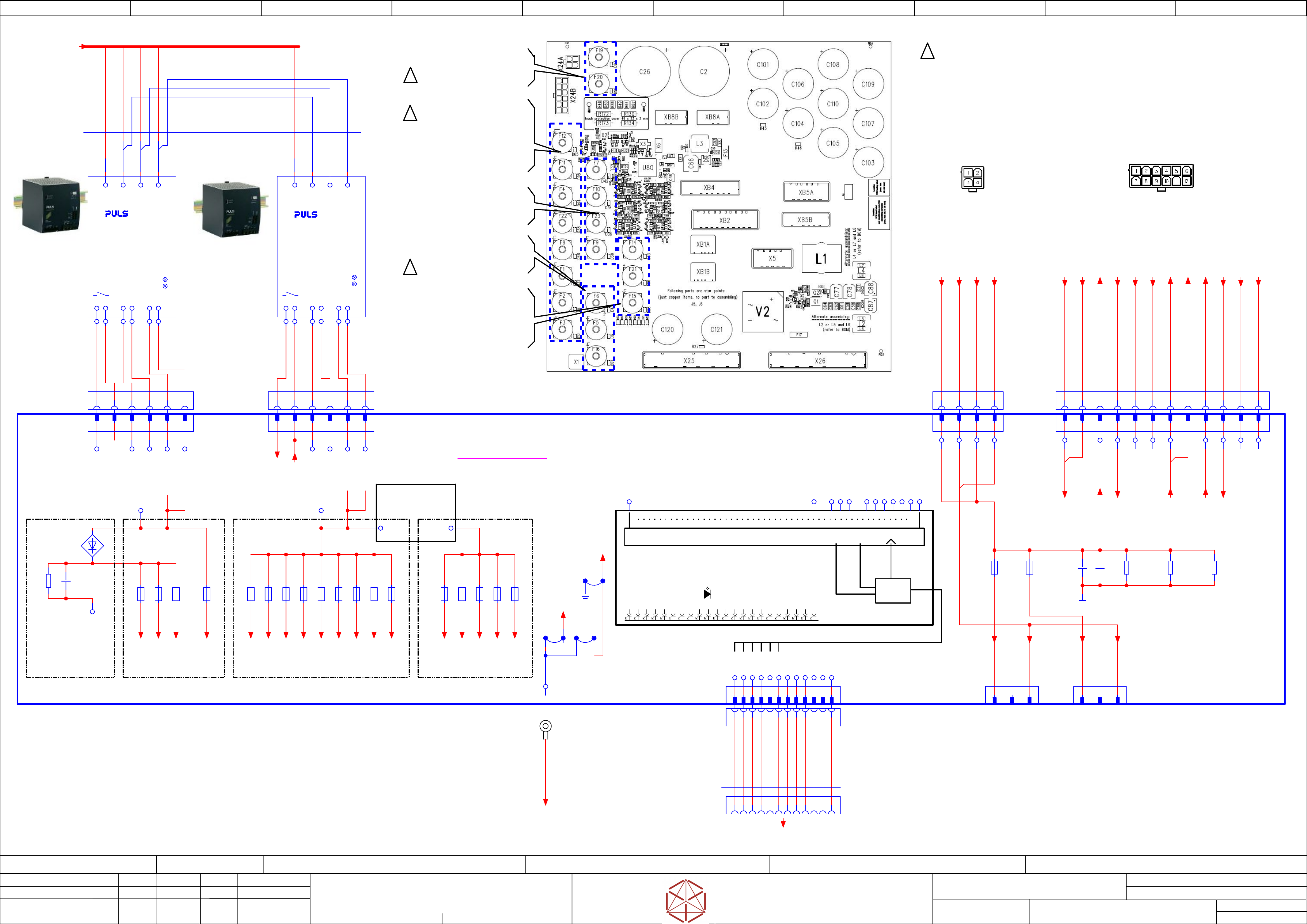
Low Voltage supply -Fusing
Replaced by
Weitergabe sowie Vervielfältigung dieser Unterlage, Verwertung und
Mitteilung des Inhalts nicht gestattet, soweit nicht ausdrücklich zugestanden.
Proprietary Data, company confidential.
All rights reserved
Copying of this document, giving it to others and the use or
communication of the contents thereof, are forbidden without express authority.
Doc. No.
0 1 2 3 4 5 6 7 8 9
Privileged business information.
Do not release
Offenders are liable to payment of damages. All rights are reserved in the
event of the grant or the registration of a utility model or design.
Zuwiederhandlungen verpflichten zu Schadenersatz. Alle Rechte vorbehalten,
insbesondere für den Fall der Patenterteilung oder GM-Eintragung vorbehalten.
Page:
Function: Power Supply SX12 V3, switched mode
==PS002=SX12_V3/44
drawing number:
03233467-010101LE3
Power_supply SMPS
GmbH & Co KG
ASM
Assembly Systems
Copyright reserved
Ed.
Original
maettig
Date
Date
Modification
Appr
12.05.2020
Name
starting MC-Nr.: 2018/Q3 G. Pingist
Size DIN A2
Sheet
44
/
3
DC Out
PS2-PE
PS2-L1
PS2-L2
PS2-L3
PS3-PE
To XB1a, XB1b, X2, Xb4, X5, Xb5a, XB5bTo Xb4, XB3, XB2, XB1a, XB1b, X24
dU = 12 V
I = 2 A
dt = 0,1 s
Serialize digital inputs
Data bus level adjust done by optocouplers
Signal level: 24 V unipolar
RED: individual voltage monitoring (on Board)
Power Supply
3AC 380-480V
DC Out
DC Voltage conversion
27V --> 24 V
240 W
RS485
driver
CLKSDATACS
To X2, Xb4, Xb5, X24
discharge-
Head-Puffer
internal connections
between GND layers
and PE layer
NOT DISCONNECTABLE
Board ID
32 bits
GREEN: Diagnostic OK
Display logic
GREEN:
RED:
Diagnostic module OK
ON: main operation OK
OFF: Error in diagnostic module
Individual error detection
ON: output voltage of channel monitored
dropped below -20% of nominal voltage
OFF: output voltage of channel monitored
within nominal limits
to Gantry interface 1
see Machine cable harness
dU = 50 V
I = 1 A
dt = 0,1 s
dt = dU/I * C
C = dt * I/dU=
= 0.1 * 1 / 50 = 0.002 [F]
GND160
3AC 380-480V
Power Supply
Overload
DC ok
Overload
DC ok
dt = dU/I * C
C = dt * I/dU=
= 0.1 * 2 / 12=
= 0.016 [F]
-X24A
Star Voltage
1 2 3 4
Calculation of
buffer Cap value
F12: CSB supply
F11: SSK-ready CSB
F4: Distributor/POWER_FAIL
F22: FCU1
F8: Y Sensor 1;
Vision Base Interface VBI 1
F1: MGCU1
F2: not used
F3: MGCU2
F7: Conveyor control
F10: internal
F23: FCU2
F9: Y Sensor 2;
Vision Base Interface VBI 2
F14: Head Supply 1
F21: Vision
F15: Head Supply 2
Fuses
to Gantry interface 2
see Machine cable harness
F19: Head Axis 1
F20: Head Axis 2
F6: PC option
F5: PC
F16: Conveyor drives
Safety Breaker
controlled
voltage
S
S
S
S
....
03104070-020101le3
-X24B
Control
1 2 3 4 5 6 7 8 9 10 11 12
-X25.FD
DC 42V in
1 2 3 4 5 6 1 2 3 4 1 2 3 4 5 6 7 8 9 10 11 12
-XB8a
Head
supply
1 2 3
-XB8b
Head
supply
1 2 3
14 13
-PS2
Conveyor and Head supply
Uout = 42 V +/- 500mV
PULS.QT40.361
03103331
- - + +
-X26.FD
X coded
DC 27 V IN
1 2 3 4 5 6
14 13
-PS3
Electronics supply
Uout = 27 V +/- 200 mV
PULS.QT40.241
03104141
- - + +
-X25
DC 42 V in
20 A con
1 2 3 4
-X26
DC 27 V in
40 A con
1 2
-FD.A1
Fuse and distribution
DC 42V in 1
DC 42V in 2
GND42
GND42
DC 27 V_1
GND27
-F5
PC
6,3 A T
-F7
Conveyor control
6.3 A T
-F6
PC_opt
6,3 A T
-F4
Distributor
6.3 A T
-F2
not used
6,3 A T
-F1
MGCU 1
6,3 A T
-F3
MGCU 2
6,3 A T
-F8
Y Sensor 1; VBI 1
6,3 A T
-F9
Y Sensor 2; VBI 2
6,3 A T
-F10
internal
6.3 A T
-F11
SSK-ready CSB
6.3 A T
-F16
Conveyor drives
10A T
-F15
Head supply 2
6.3 A T
-F12
CSB supply
6.3 A T
-F14
Head supply 1
6.3 A T
-F21
Vision
6.3 A T
3
-C101_110
10x 2200µF
+
GND
4
DC 27 V-2
GND27
55 6
+42V
-F23
FCU 2
10 A T
-F22
FCU 1
10 A T
+27V
F1
PWR_Fail_27V_in (default: FAIL)
PWR_Fail_42V_in (default: FAIL)
F23
PWR_Fail_in (default: FAIL)
PE
GND27
PE
X1:PE
6
>27V >24V
K1_OK (default: NOK)
K2_OK (default: NOK)
ID0
ID1
ID2
ID3
K2_OK (default: NOK)
6x(2x1,5/4x4,0)
Single wire
03110991-02
-W7
BK 4,0
BK 4,0
BK 4,0
BK 4,0
BK 1,5
BK 1,5
-F20
Gantry 2
-F19
Gantry 1
-C26
2x 1200µF
Buffer 160 V
+
-R48
3x 47K/0,5W
For safe discharge
1 minute
board standalone
only
+ 160 V
GND160
+ 42 V
+ 42 V Safety
PCC_PWR_OK
PWR_ENA
+ 24 V
CH1_OK
CH2_OK
24V_Safety
+ 160 V
GND
+ 24 V
GND160
1
GND160
-C2
+
-R49
47K/0,5W
-J2
-J3
LGND
GND27
-J1
-V2
-R45_46
2x10K 1,4W
-R50
47K/0,5W
530 mm
6x(2x1,5/4x4,0)
Single wire
03110992-02
-W8
BK 4,0
BK 4,0
BK 4,0
BK 4,0
BK 1,5
BK 1,5
PWR_OK_PS2
PE L1 L2 L3 PE L1 L2 L3
1 2 3 4 5 6 7 8 9 10 11 12
MOSI
CLK
/CS
CS
/CLK
/MOSI
-X2
1 2 3 4 5 6 7 8 9
-X2.FD
Diagnostic
serial interface
NC
NC
10 11 12
+ 5V
GND
NC
GND
1
-X11qp
Diagnostic
serial interface
Distributor
Socket housing DF11 12-pin 2mm pitch
2 3 4 5 6 7 8 9
10 11 12
WH
BN
GN
YE
GY
BU
RD
BK
VT
GYPK
RDBU
3900 mm
12x0,14
UNITRONIC® LiYY A
03119738-01
-W24
PK
Safety 160V in
-X24A.FD
Control
/44.8
-X24B.FD
-X1.FD
Cable lug 2.5 mm² M5
crimp 2.5 mm²
M5
Single wire connections
3x2,5
Single core
#03121661-W11.2
2,5 BK
2,5 BK
2,5 BK
2,5 BK
2,5 BK
2,5 BK
-Mains-Sub-1
/-X302:1 /43.0
PE_FD.A1
/42.8
42V(F14)
==CH+PS/52.5
42V(F15)
==CH+PS/52.8
42V(F21)
==CH+PS/51.2
==CH+PS/52.5
42V(F16)
/44.8
27V(F1)
==CH+PS/52.0
27V(F2)
==CH+PS/52.1
27V(F3)
==CH+PS/52.2
27V(F5)
==CH+PS/51.1
27V(F6)
==CH+PS/51.2
27V(F8)
==CH+PS/52.5
27V(F9)
==CH+PS/52.8
27V(F22)
==CH+PS/51.5
27V(F23)
==CH+PS/51.5
24V(F4)
==CH+PS/51.1
24V(F11)
/44.8
24V(F10)
/44.2
24V(F12)
/44.9
24V(F7)
==CH+PS/51.8
PWR_OK
==CH+PS/51.8
==CH+PS/52.1
24V(F10)
/44.3
42V(F16)_S
==CH+PS/51.8
24V(F12)_S
==CH+PS/51.8
PWR_ENA
==CH+PS/51.9
==CH+PS/52.1
24V(F12)
/44.3
24V(F11)
/44.3
42V(F16)
/44.1
==+FD-42V(F16).1
==CH+CSB/53.8
==+FD-PWR_ENA
==CH+CSB/53.8
==+FD-42V(F16).2
==CH+CSB/53.8
==+FD-24V(F11)
==CH+CSB/53.8
Safety supply
==+FD-GND24
==CH+CSB/53.8
==+FD-42V(F16)_S.1
==CH+CSB/53.7
DC 42 V power supply
==+FD-42V(F16)_S.2
==CH+CSB/53.8
DC 42 V power supply
==+FD-PCC_PWR_OK
==CH+CSB/53.8
==+FD-24V(F12)_S
==CH+CSB/53.9
==+FD-24V(F12)
==CH+CSB/53.9
DC 42 V power supply
==+FD-CH1-OK
==CH+CSB/53.9
==+FD-CH2-OK
==CH+CSB/53.9
==+FD-DC160V_S.1
==CH+CSB/53.6
==+FD-DC160V_S.2
==CH+CSB/53.6
==+FD-GND160.1
==CH+CSB/53.6
==+FD-GND160.2
==CH+CSB/53.7
-RS485_DIAG_FD
Software diagnostic to I/O-CU
==DI+DI/48.2
GND42
==CH+PS/51.2
==CH+PS/52.5
GND27
==CH+PS/51.1
==CH+PS/52.1
P160V(F19)
==CH+PS/52.4
GND160.1
==CH+PS/52.4
P160V(F20)
==CH+PS/52.7
GND160.2
==CH+PS/52.7
electric_schematic_SX12_V3
Editor
Original
90013315-010101LE3
maettig
Date
Date
Replaced by
Vacuum Pump Control SX12 V3
Optional
03233467-010101LE3
Modification
Approved
Replaced by
12.05.2020
Name
Weitergabe sowie Vervielfältigung dieser Unterlage, Verwertung und
Mitteilung des Inhalts nicht gestattet, soweit nicht ausdrücklich zugestanden.
Proprietary Data, company confidential.
All rights reserved
Copying of this document, giving it to others and the use or
communication of the contents thereof, are forbidden without express authority.
Doc. No.
GmbH & Co KG
ASM
Assembly Systems
Copyright reserved
0 1 2 3 4 5 6 7 8 9
Privileged business information.
Do not release
Offenders are liable to payment of damages. All rights are reserved in the
event of the grant or the registration of a utility model or design.
Zuwiederhandlungen verpflichten zu Schadenersatz. Alle Rechte vorbehalten,
insbesondere für den Fall der Patenterteilung oder GM-Eintragung vorbehalten.
Page:
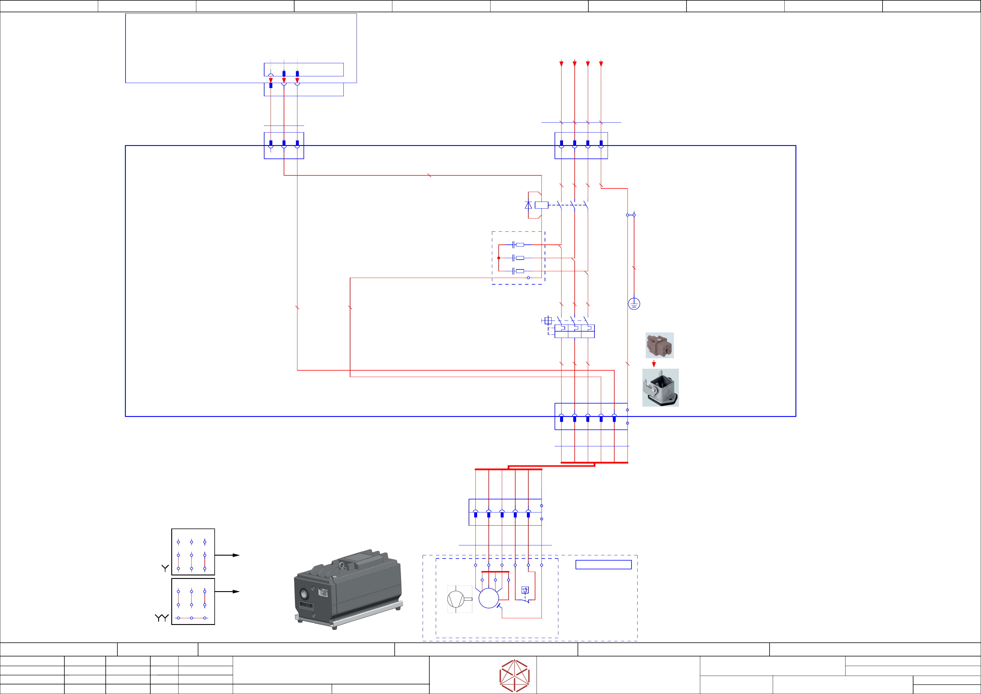
Function: Power Supply SX12 V3, switched mode
==PS002=SX12_V3+VAC_P/45
drawing number:
Size DIN A2
Sheet
45
/
1
starting MC-Nr.: 2018/Q3 G. Pingist
Note!
Drive rotation CCW required
for vacuum generation
L1 --> W1
L2 --> V1
L3 --> U1
Please check correct
function of vacuum pump
after connection!
doppel star
connection
Line-voltage =
200-230VAC
star connection
Line-voltage =
380-415VAC
Line Line Line
Line Line Line
Vacuumpump incl. cable
03212135
Power Supply
< --------direct_mounting---------- >
1
2
3
4
5
GNYE
A1
A2
-K1
Vacuum Pump Control
SIE.3RT2015-1FB42
03114295
/45.5
/45.5
/45.5
1
2
3
4
5
6
-X103
MATE-N-LOK Socket 3-pin
2 3
-X105
MATE-N-LOK Socket 4-pin
1 2 3 4
A
K
1
-PE
Cable-lug M5
Retaining-plate
+03232030
-qr
Vacuum Pump Control
SX12 V3
==OVGR+/5
==OV+PS002/10.2
-X105
Power Vacuum Pump
1 2 3 4
1,5 BK
1,5 BK
1,5 BK
1,5 GNYE
1,5 BK
1,5 BK
1,5 BK
1,5 GNYE
1,5 BK
1,5 BK
1,5 BK
0,75 BK
0,75 BK
0,75 BK
B1.1 B1.2
U2 W2V2
PEV1 U1W1
-M1
PE
3~
M
-X1.VP
Male insert CQM 05-pin + PE 16A
1 2 43 5
1400 mm
7G0,75
ÖLFLEX® 150
03202514
-W1
-B1
bimetallic-switch
150°C
21
==FLUID+-VAC1
Pneumatics
==FLUID+/129.4
1 2 3 4 5 GNYE
2
T1.V
1
T1.U
3
T1.W
-X106
Power
Vacuum pump
Female insert CQF 05-pin + PE 16A
Bulkhead housing CK 03 I
4
B1.1
5
B1.2
-X2.PE
1 Ground terminal block 4-cond. 279-837
1,5 GNYE
-X103
Control Vacuum Pump
1 2 3
-X17qa
21 5 643
2
31
-X17
Control Vaccum Pump
-qa
Distributor unit SX1/2 V3
03218436
5 64
3880 mm
3x0,34
Unitronic
03072544
-W1
WHBN GN
V1W1 U1
U3V3W3
U2V2W2
V1W1 U1
U3V3W3
U2V2W2
1
2
3
4
5
6
-QM1
circuit protection
switch, 3pol.
CLASS10, 2,2 - 3,2A
SIE.3RV2011-1DA10
ajdusting=2,2 A
03158435
Option:
Line Voltage 200-220V:
QM1 200-230VAC:
3RV2011-1FA10 (adjusting 4A)
03116399
I>
I>
I>
-VACP1
vacuum pump Becker VX4.25_IE3
0,75KW, 25m³/h
03211684
-RC1
2Tx
-RC2
4Tx
-RC3
6Tx
-RC1
EMC supression module 3-phase 5.5 kW
SIE.3RT19 16-1PA1
03088931
A2
2
V2
1
U2
3
W2
-X1.VP
Female insert CQF 05-pin + PE 16A
Connector housing with lever ILME CK 03 VGS
PE
-X106
Male insert CQM 05-pin + PE 16A
Connector housing ILME MKA V20
1 2 43 5
PE
4
5
GNYE
2
1
3
3 m
6G1,0
ÖLFLEX® 150
-0103231357
-W1
Vacuum-Pump IE3
Extension-Cable
4
B2.1
5
B2.2
PE
PE
4x1,5
Single core
03231317
-W1
1,5 BK 400 mm
1,5 BK 400 mm
1,5 BK 400 mm
1,5 GNYE 420 mm
1
==PS+-VP_PE
+/42.8
==PS+-VP_L3
+/42.8
==PS+-VP_L2
+/42.8
==PS+-VP_L1
+/42.7
Female insert
==DI+-Vaccumpump_ON
==DI+DI/48.9
==DI+-24V_VAC
==DI+DI/48.8
==DI+-GND_VAC
==DI+DI/48.9
electric_schematic_SX12_V3
90013315-010101LE3
Replaced by
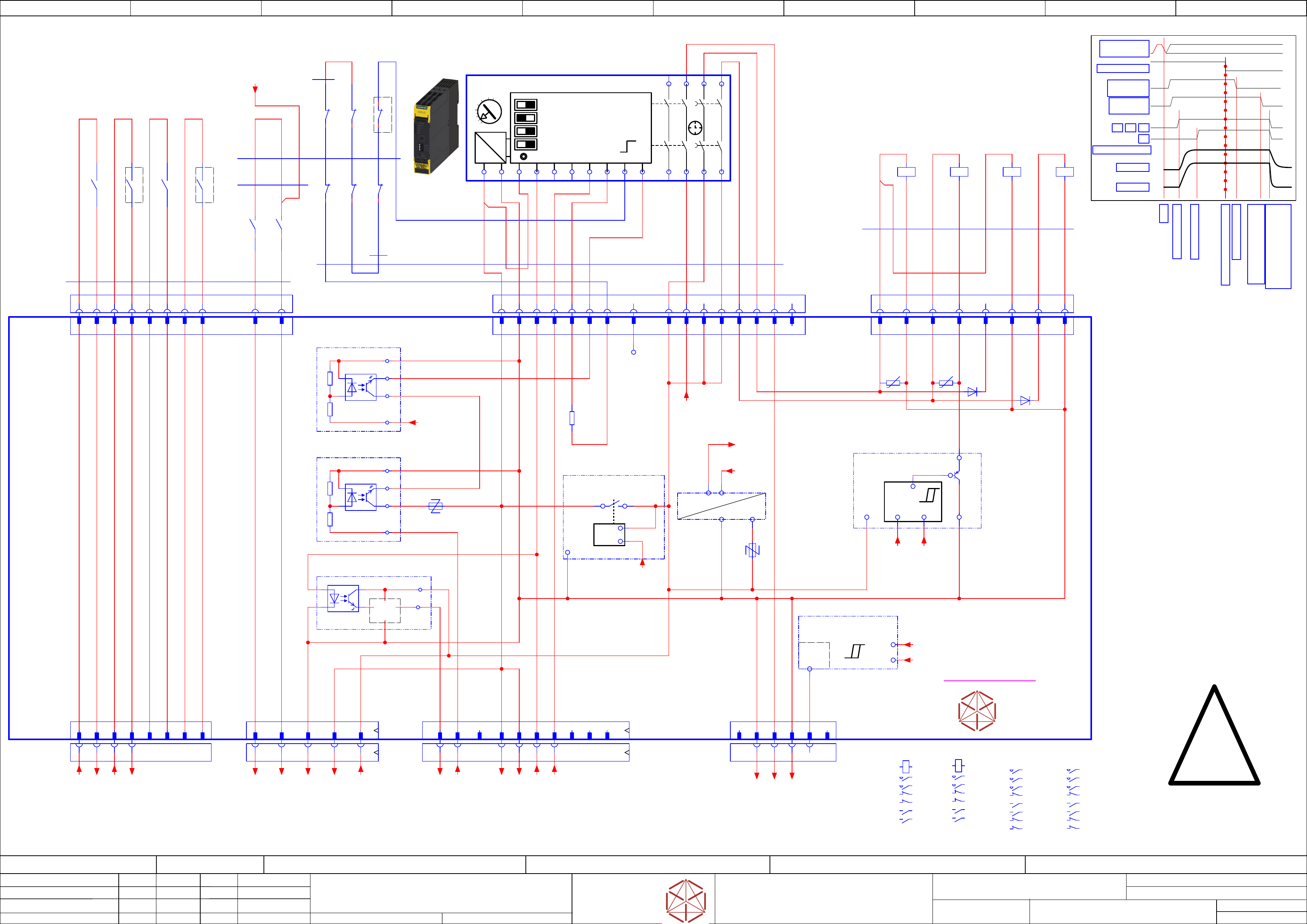
Contactor based safety breaker: logic
Replaced by
Weitergabe sowie Vervielfältigung dieser Unterlage, Verwertung und
Mitteilung des Inhalts nicht gestattet, soweit nicht ausdrücklich zugestanden.
Proprietary Data, company confidential.
All rights reserved
Copying of this document, giving it to others and the use or
communication of the contents thereof, are forbidden without express authority.
Doc. No.
0 1 2 3 4 5 6 7 8 9
Privileged business information.
Do not release
Offenders are liable to payment of damages. All rights are reserved in the
event of the grant or the registration of a utility model or design.
Zuwiederhandlungen verpflichten zu Schadenersatz. Alle Rechte vorbehalten,
insbesondere für den Fall der Patenterteilung oder GM-Eintragung vorbehalten.
Page:
Function:
==CSB=SX12_V3/46
drawing number:
03112066-020101LE3
Control safety breaker
GmbH & Co KG
ASM
Assembly Systems
Copyright reserved
Ed.
Original
maettig
Date
Date
Modification
Appr
12.05.2020
Name
starting MC-Nr.: 2018/Q3 G. Pingist
Size DIN A2
Sheet
46
/
2
- not used -
S
Safety component!
Use specified parts only!
LOGIC
=~
=
+ -
1 | Autostart/Monitored Start
2 | Cross Fault Detection Off/On
3 | 2 single ch. sensors / 1 double channel Sensor
4 | Startup Test Yes/No
SET / RESET
T
Set delay time
to 140 ms +/- 40 ms
0,05
0,5
1
2
2,5
3s
Timing chart
Start
Precharge done
Emergency STOP event
K1,K2, K3, K4 off delay;
Discharge external Cap
-->Power off
Safety relais off
Safety relaais off delay
> 100 ms; <180 ms
Precharge start
DC 300 V
DC 160 V
K2
POWER_ENABLE
K1 K4K3
PCC output
delayed
PCC output
not delayed
EMG_Loop_OK
SW_CTRL_ON
Start
Changes:
Use Standard NC contact at aux block at K3 for discharge
User NC contact at contactor K4 for discharge
Remarks
1. DIAG_K_N is blocking START signal
if pre- or discharge resistor monitoring
signals error (overheating or disconnection)
2. DIAG_K_RD is disconnecting 24V supply
of safety relais if discharge monitoring
reports discharge error.
3. Safety relais supply voltage is disconnected
if there is undervoltage in unit suply voltage.
Supply voltage can be monitored at output
PCC-POWER-OK
4. Set safety relais (K5) to dalay time between
140 ms and 200 ms.
Delay time shorter will cause MGCU error
'Link voltage supply error' due to voltage
increase while drives breaking phase.
Delay time longer will cause increase in
danger to operator if cover is opened.
5. In General:
Press STOP button first prior to open cover.
STOP button will not trigger safety breaker but
will stop motion avoiding both danger to motion
and malfunction of MGCU DC link supply.
6. Make sure to connect T1 of PCB to main
grounding terminal. If this connection is missing
there will be no discharge functionality and
Safety breaker unit will not activate output
voltages!
24V0 Safety_unit supply
ITS4141
Load-switch
03108631-010301LE3
ITS4141
Load-switch
&
GND_Safety
24V_PCC
&
-F2
-F1
&
not used
2 4
-X31.CSB
Safety-controlled
DC 24V
31 5 65A5 B181615 5 B5
-X24B.CSB
Safety control
signals to FDB
-X29.CSB
Safety Loop
& Signals
extern
A67 B2 B3 B4A4 B6 A31 2 3 4 5 6 7 8
-X30.CSB
Safety
Loop Extern
A1
INK
IN1
IN2
A2
13
23
37
47
INF
INS
38
48
T2
T1
PAR
-K5
Safety relay 2-chanel
24V AC
03114826-
Siemens
3SK1121-xCB41
14
24
Safety Relais connect
-X100.CSB
1 2 3 4 5 6 7 8
nc
9 10 11
nc
12 13 14 15 16
nc
-K1
Relay Safety
300V, 160V
A1
A2
A1 A2
2 1
/47.3
4 3
/47.4
2122
/46.2
3231
/46.2
1413
4443
/46.1
SIE.3TC4417-0AB4
-K3
Relay Safety
42V, 24V
A1
A2
1 2
/47.9
3 4
/47.8
6 5
/47.9
2221
/47.2
5453
/46.1
6463
/46.0
7271
8281
/46.2
EAT.DILA32-XHIR22
EAT.DILM17-01(RDC24)
-K4
Relay
Pre-charge
300V, 160V
A1
A2
1 2
/47.1
3 4
5 6
/47.2
2221
/46.2
5453
/46.1
6463
/46.1
7271
/47.1
8281
EAT.DILA32-XHIR22
EAT.DILM17-01(RDC24)
1 2 81 2 3 4 5 6 7 8 9 10 65 7
-X28.CSB
AuxContacts
-X27.CSB
Safety
contactor
-K2
Relay Safety
300V, 160V;
Power enable
A1
A2
A1 A2
2 1
/47.3
4 3
/47.4
2221
/46.2
3132
/46.2
1413
/47.8
4443
/46.2
SIE.3TC4417-0AB4
3 4
-K1
43
44
-K4
21
22
-K1
22
21
-K1
31
32
-K2
21
22
-K2
32
31
-K2
43
44
Auxiliary contacts
10x0,5
SIngle core
#03119736-W5
YE
YE
YE
YE
YE
YE
YE
YE
Cable safety relais
14x0,5
Single core
#03119737-W6
PK
PK
PK
YE
BN
WH
YE
YE
YE
BN
YE
BN
BN
Cable Contactor Control
450/750V
7x0,5
Single core MULTI-STANDARD SC 2.1
#03119735-W4
PK
PK
PK
PK
WH
WH
WH
WH
YE
YE
BN
0,5 BN
0,5 YE
0,5 YE
0,5 YE
0,5 YE
Single wire connections
1x0,5
#03121398-W7.2
0,5 YE
0,5 BN
YE
Single wire connections
1x0,5
Single core
#03121398-W7.4
OUT2_ND
DC 24V Safety controlled PL=d
3
GND Safety
8
EMG_Loop_OK
A5
Loop2-IN
B1
nc
B2
Loop1_IN
A31 2 3 4 5 6 7 8
15
OUT2_ND
9
24V0
10
24Vext
11
24V0
12
24V0
13
OUT2_D
16
OUT1_ND (nc)
1
K1-A1
GND Safety
2
GND Safety
4
2
GND
8
GND
1 2 3 4 5 6 7 8 9 10
CH2-OK
16
CH1-OK
15
14
OUT1_D
6
GND
24V-PCC
B5
24V-PCC
B6
5
A3-K1
7
K4-A1
nc
1
PPWR-present
5
nc
6
-A2
Safety breaker unit
PCB Pre-/discharge assembly
-X28
AuxContacts in
-X100
Safety relais connect
-X27
Safety
contactor
-X30
Safety
Loop extern
-X24B
Safety
control signals
-X29
Safety Loop
& Signals
-X31
Auxiliary
(RFU signals)
3
K2-A1
4
GND/K5
START_SIG
Safety Start
Signal input
A6
-Out
-PPWR.PRESENT
Voltage-Trigger
300V/160V PPWR-present
(300V > 60V && 160V > 60V)
P300V
P160V
-K2 Start B
-
+
+
in
out
1
Supply
2
GND
3
Loop1_IN
4
Loop2_IN
5
T2
6
START
7
TestLoopIn
8
nc
GND
DIAGN_K_N
-K3 Start A
-
+
+
in
out
GND
START_SIG
24V0
Safety unit
5
+
+
-
-K1
Safety loop
closed signal
24V0
L_CLSD
24V_PCC
7
nc
A4
nc
B3
nc
B4
-R42
60VAC(100mW)
-R43
60VAC(100mW)
-D18
-D50
-R128
0R
Test_loop_IN
-P300.pbc
Voltage-Trigger
300V precharge bypass control
Out
GND
Supply
24V.Safe
Safe DC
internal supply
24VSafe
24V0
24V_PCC
PCC supply
undervoltage lockout
OUT
24V_PCC
IN
24V0
DIAG
U_Mon
-K4
53
54
-K4
63
64
-K3
53
54
-K3
63
64
-K3
81
82
Single wire connections
#03121398-W7.1
6x0,5
Cable Low Voltage Control
#03119733-W2.3
2x0,5
==+-GND.2
==+-GND.3
==+-24V_S
-DI0_Safety_Loop_OK
==CH+CSB/53.4
-24V(F11)
==CH+CSB/53.8
-GND.1
==CH+CSB/53.8
-Safety_Loop2_End
==CH+CSB/53.3
-CH1_OK
==CH+CSB/53.9
-CH2_OK
==CH+CSB/53.9
-Safety_Loop1_Begin
==CH+CSB/53.3
-SW_Control_ON
==CH+CSB/53.4
-PCC_PWR_OK
==CH+CSB/53.8
-Safety_Loop2_Begin
==CH+CSB/53.3
-Safety_Loop1_End
==CH+CSB/53.3
-Safety_Loop1_ext.in
==CH+CSB/53.5
-Safety_Loop1_ext.out
==CH+CSB/53.5
-Safety_Loop2_ext.in
==CH+CSB/53.5
-Safety_Loop2_ext.out
==CH+CSB/53.5
==+-24V_F12_Aux
/47.7
-P300V
/47.1
-P160V
/47.4
==+-DIAGN_K_N
24V-Supply
/47.7
DC 24 V power supply
to external signals
VDIFFMON1
300V
/47.2
VDIFFMON2
160V
/47.2
24VSafe
Safe supply
/47.6
P_GND
Power Ground
/47.6
DIAGN_RD_N
/47.5