ASM贴片机SX2机型电路图.pdf - 第52页
electric_schematic_SX12_V3 90013315-010101LE3 Replaced by CAN I/O Unit A1(qb) Replaced by Weitergabe sowie Vervielfältigung dieser Unterlage, Verwertung und Mitteilung des Inhalts nicht gestattet, soweit nicht ausdrückli…
electric_schematic_SX12_V3
90013315-010101LE3
Replaced by
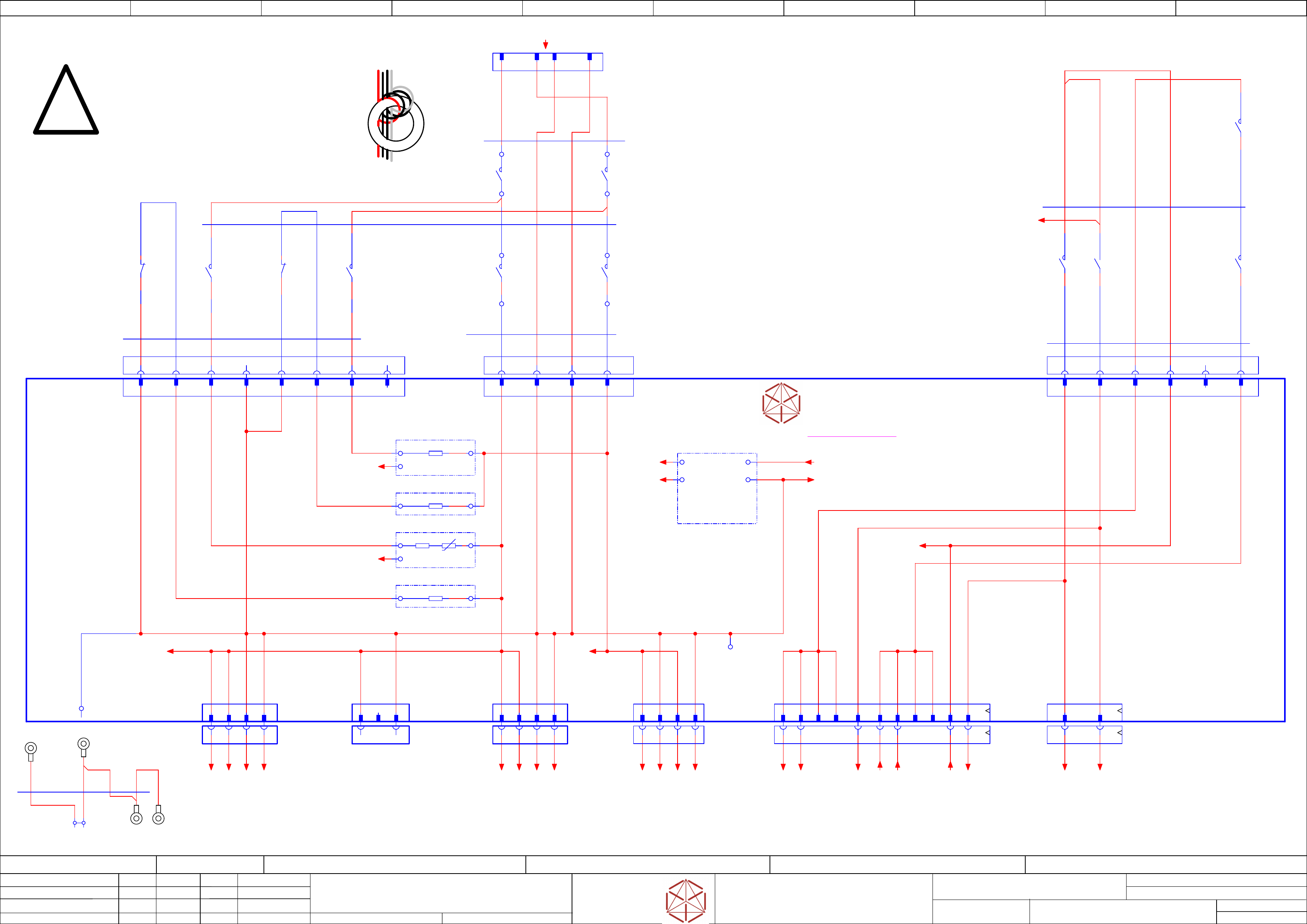
Contactor based safety breaker: power
Replaced by
Weitergabe sowie Vervielfältigung dieser Unterlage, Verwertung und
Mitteilung des Inhalts nicht gestattet, soweit nicht ausdrücklich zugestanden.
Proprietary Data, company confidential.
All rights reserved
Copying of this document, giving it to others and the use or
communication of the contents thereof, are forbidden without express authority.
Doc. No.
0 1 2 3 4 5 6 7 8 9
Privileged business information.
Do not release
Offenders are liable to payment of damages. All rights are reserved in the
event of the grant or the registration of a utility model or design.
Zuwiederhandlungen verpflichten zu Schadenersatz. Alle Rechte vorbehalten,
insbesondere für den Fall der Patenterteilung oder GM-Eintragung vorbehalten.
Page:
Function:
==CSB=SX12_V3/47
drawing number:
03112066-020101LE3
Control safety breaker
GmbH & Co KG
ASM
Assembly Systems
Copyright reserved
Ed.
Original
schnedlitz
Date
Date
Modification
Appr
30.04.2020
Name
starting MC-Nr.: 2018/Q3 G. Pingist
Size DIN A2
Sheet
47
/
2
- not used -
-X3
Cable lug
crimp 2.5 mm²
M5
-X2
Cable lug
crimp 2.5 mm²
M5
-X4
Cable lug
crimp 2.5 mm²
M5
apply 1 winding
near X19.CSB
use all wires
S
Safety component!
Use specified parts only!
300V
PGND
03108631-010301le3
-X1
Cable lug
crimp 2.5 mm²
M5
A2 A1
-X21.CSB
300V Power
3 41 2
-X22.CSB
300V Power
-X22b.CSB
300V Power
-X29.CSB
Safety Loop
& Signals
extern
1 3 3 41 2
-X24B.CSB
Safety control
signals to FDB
DC42V IN/OUT
1 2 9 10 13 1463 4 11 122
-X24A.CSB
Star Voltage
1 2 3 4
-X1(PE)
stripping 5mm
1
Single connections CSB
Single Core
#03121398-W7.5
GNYE
GNYE
GNYE
BK
A1 A2 B1 B2
-X20.CSB
Power-in
300V, 160V B3B1 B2
-X25.CSB
Low voltage control A1 A2 A3
-K1
Switch
160V
4
3
-K1
Switch
300V
2
1
-K2
Switch
300V
2
1
-K2
Switch
160V
4
3
-K3
Switch
24V
3
4
-K3
Switch
42V
1
2
-K3
Switch
42V
6
5
-K2
Switch
24V
13
14
-K4
Pre-
charge
160V
5
6
-K4
Pre-
charge
300V
1
2
B3B1 B2 B4
-X26.CSB
Pre/Discharge control
K1, K2, K4 A1 A2 A3 A4
#03119732-X19.CSB
Power-in
300V, 160V
B1
P-GND
A1
DC 300V in
B3
P-GND
A3
DC 160V in
Cable Pre/Discharge
6x1,5
500 mm
Single core
#03119734-W3
BK
BK
GY
RD
BK
BK
Cable Power input
4x2,5
390 mm
Single Core
#03119732-W1
WH
WH
RD
GY
4x2,5
Single Core
#03119732-W1
Cable Low Voltage Control
450/750V
5x
Single core MULTI-STANDARD SC 2.1
#03119733-W2.1
GY
BN
GY
YE
YE
GY
RD
Cable Low Voltage Control
450/750V
2x1,5
Single core MULTI-STANDARD SC 2.1
#03119733-W2.2
BN
GY
Single wire connections
4x2,5
Single wire
#03121398-W7.3
GY
GY
RD
RD
-K3
DISCHARGE
CH2
21
22
P300V
1
P300V
2
PGND
3
PGND
4 104
DC 160V out
1
DC 160V out
3
GND Power
2
GND Power
4
B2
Power 160V
B1
Power GND
A2
Power GND
A1
Power300V
24V_SW
safety_controlled PL=c
A2
PWR_EN
Power enabled
A1
-X20
Power-in
300V, 160V
921
B1
24V_Supply
B3
P42V_OUT
B2
-X25
Low voltage control
A3
P42V_IN
A2
PWR_ENA
A1
24V_SW
-X21
300V Power
-X22
300V Power
-X22B
300V Power
-X24A
Safety
switched 160V
-X29
Safety Loop
& Signals
T1
PE
P300V
1
NC
2
PGND
3
P300V
1
P300V
2
PGND
3
PGND
4
-X24B
Safety
control signals
42V IN/OUT
B1
P_GND
B3
160V_PRE
B2
DISCHARGE CONT2
B4
n/c
-X26
Pre/Discharge control
A4
P_GND
A3
300V_PRE
A2
DISCHARGE CONT1
A1
P_GND
DC 42 V safety-
controlled OUT
3
Power enabled
6 12
DC 42 V safety-
controlled IN
11
24V_SW
14
24V Supppy
13
-T1:1
PGND
-DIAG
Precharge and discharge
resistor diagnostic
and error detection
Out11
Out22 Supply 3
GND 4
-Precharging.160V
-Precharging.300V
-Discharge.160V
-R
-R
-R
-R_Th
Voltage monitor
Voltage monitor
-R
-Discharge.300V
-A2
Safety breaker unit
PCB Pre-/discharge assembly
-K4
DISCHARGE
CH1
71
72
-PWR_ENA
==CH+CSB/53.8
-DC160V_S.1
==CH+CSB/53.6
-GND300.1
==CH+CSB/53.0
-GND300.2
==CH+CSB/53.1
-DC300V.1
==CH+CSB/53.0
-DC300V.2
==CH+CSB/53.0
-GND300.3
==CH+CSB/53.2
-GND300.4
-DC300V.3
==CH+CSB/53.2
-DC300V.4
-DC160V_S.2
==CH+CSB/53.6
-GND160.1
==CH+CSB/53.6
-GND160.2
==CH+CSB/53.7
-24V(F12)
==CH+CSB/53.9
-DC24V(F12)_S_DIS
==CH+CSB/53.4
-DI13_PWR_ENA
==CH+CSB/53.3
-42V(F16)-in-1
==CH+CSB/53.8
-42V(F16)-in-2
==CH+CSB/53.8
-DC42V(F16)_S.2
==CH+CSB/53.7
-DC42V(F16)_S.1
==CH+CSB/53.7
-DC24V(F12)_S
==CH+CSB/53.9
==+-24V_F12_Aux
-K2:43 /46.1
24V-Supply
/46.5
-P300V
/46.6
-P160V
/46.6
DIAGN_RD_N
/46.4
DIAGN_K_N
24VSafe
/46.5
Safe supply
P_GND
/46.5
Power Ground
VDIFFMON1
/46.6
VDIFFMON2
/46.7
-PWR-160/300V
==PS002/43.0
electric_schematic_SX12_V3
90013315-010101LE3
Replaced by
CAN I/O Unit A1(qb)
Replaced by
Weitergabe sowie Vervielfältigung dieser Unterlage, Verwertung und
Mitteilung des Inhalts nicht gestattet, soweit nicht ausdrücklich zugestanden.
Proprietary Data, company confidential.
All rights reserved
Copying of this document, giving it to others and the use or
communication of the contents thereof, are forbidden without express authority.
Doc. No.
0 1 2 3 4 5 6 7 8 9
Privileged business information.
Do not release
Offenders are liable to payment of damages. All rights are reserved in the
event of the grant or the registration of a utility model or design.
Zuwiederhandlungen verpflichten zu Schadenersatz. Alle Rechte vorbehalten,
insbesondere für den Fall der Patenterteilung oder GM-Eintragung vorbehalten.
Page:
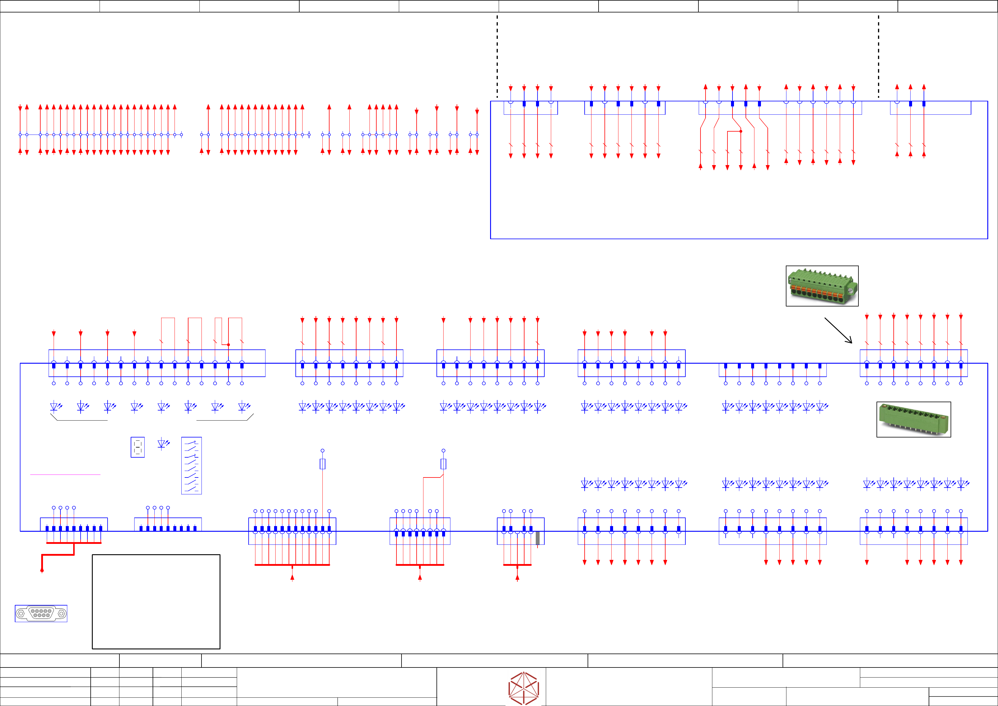
Function: Distributor
==DI=SX12_V3+DI/48
drawing number:
03218436-030101LE3
Distributor_SX1(2)_V3
GmbH & Co KG
ASM
Assembly Systems
Copyright reserved
Ed.
Original
Langerd
Date
Date
Modification
Appr
14.05.2020
Name
starting MC-Nr.: 2018/Q3 G. Pingist
Size DIN A2
Sheet
48
/
3
-X14
RS485 for PSU
1 2 3 4 5 6 87
-H1
Display
-H3
RD
Reset
1 2 4 53
5
KEY
MC-identifcation(X2/X4)
reserved
MC-identifcation (TX/XS)
reserved
reserved
Serial-bootstrap
CAN-bootstrap
Reset-state
Phoenix: 1830651
-X9
Note:
Header with
Screwable
flange.
Note:
The I/O control unit III cpl. (03120301-xx)
is not part of the distributor (03218436-xx).
-X3qb
MINI COMBICON FK-MCP 1,5/ 8-ST-3,81 8-pin
PXC.1851106
1 2 3 4 5 6 7 8
--- not used ---
-X9qb
Plug component FK-MCP 1,5/ 8-STF-3,81 8-pin
PXC.1851290
1 2 3 4 5 6 7 8
not used
1 2 3 4 6 7 8 129 10 115
-X14qb
RS485/PSU
RJ45
1 2 3 4 5 6 7 8
1 2 3 4 6 7 85
<<< to Power Supply >>><<< Terminal blocks 1 - 29 >>>
03119874-030101LE3
Note:
Connector
version
with screw
flange.
Phoenix: 1851290
-X9qb
Digital IN, Fan monitoring
1 2 3 4 6 7 8 95
Note for terminal block -X1qa:
“Adjacent jumper” between the
following terminal blocks:
24V(F4) 24V(F12)_S
1.) 14 and 15 7.) 23 and 24
2.) 15 and 16 8.) 24 and 25
3.) 16 and 17
4.) 17 and 18
5.) 18 and 19
6.) 19 and 20
-X3
Data In 1
1 2 3 4 5 6 7 8
-X4
Data In 2
1 2 3 4 5 6 7 8
-X5
Data In 3
1 2 3 4 5 6 7 8
-X6
Data In 4
1 2 3 4 5 6 7 8
-X9
Power
1 2 3 4 5 6 7 8
-X8
Data Out 2
1 2 3 4 5 6 7 8
-X7
Data Out 1
1 2 3 4 5 6 7 8
DI3
DI7
DI6
DI5
DI4
DI2
DI1
DI0
DI11
DI15
DI14
DI13
DI12
DI10
DI9
DI8
DI19
DI23
DI22
DI21
DI20
DI18
DI17
DI16
DI27
DI31
DI30
DI29
DI28
DI26
DI25
DI24
24V
GND
GND
GND
GND
24V
24V
24V
DO14
DO13
DO12
DO11
DO10
DO9
DO8
DO15
DO6
DO5
DO4
DO3
DO2
DO1
DO0
DO7
-A1(qb)
I/O Control Unit III
03120301
-X2
CAN2
1
NC
4
NC
5
NC
8
NC
9
NC
2 36 7
-X1
CAN1
1
NC
2 3 4
NC
5
NC
6 7 8
NC
9
NC
GND
GND
CAN2_L
CAN2_H
GND
GND
CAN1_L
CAN1_H
RS485_OUT_NINV
+24V
RS485_OUT_INV
RS485_IN_INV
RS485_IN_NINV
GND
GND
-X11
FDB
serial interface
FUSE_IN_MISO_NINV
FUSE_IN_MISO_INV
FUSE_OUT_CLK_NINV
FUSE_OUT_CLK_INV
FUSE_OUT_LATCH_NINV
FUSE_OUT_LATCH_INV
MTSR
EXT1
EXT2
DETECT_DISTRBRD
+5V
GND
-F2 -F3
1 2 3 4 5 6 7 8 9 10 11 12
-X19
RS485 for FC
RS485HD_A
1 2 4 5
-X19:GND
RS485HD_B
GND
63
-X19.DI
RS485/FC
1 32 45
-X18
Data In 5
< ---- NPN-INPUT (low_active) ---- >
1 2 3 4 5 6 7 8
/DI35
/DI39
/DI38
/DI37
/DI36
/DI34
/DI33
/DI32
9 10 11 12 13 14 15
GND
GND
GND
GND
GND
GND
GND
-X17
Data Out 3
1 2 3 4 5 6 7 8
DO22
DO21
DO20
DO19
DO18
DO17
DO16
DO23
2
4
5
6
7
8
-S1
1
3
-X4qb
MINI COMBICON FK-MCP 1,5/ 8-ST-3,81 8-pin
PXC.1851106
1 2
NC
3 4 5 6 7 8
-X5qb
MINI COMBICON FK-MCP 1,5/ 8-ST-3,81 8-pin
PXC.1851106
1 2 3 4 5
NC
6 7 8
NC
1,0 WH
1,0 WH
1,0 WH
1,0 WH
1,0 BN
1,0 BN
1,0 BN
1,0 BN
1 2 3 4 5 6 7 8 9 10 11 12
-X11qb
Fuse-Diagnostic
serial interface
-X7qb
MINI COMBICON FK-MCP 1,5/ 8-ST-3,81 8-pin
PXC.1851106
765432
1 8
NC
-X8qb
MINI COMBICON FK-MCP 1,5/ 8-ST-3,81 8-pin
PXC.1851106
1
NC
2
NC
3
NC
4 5 6 7 8
-X17qa
Vaccum_Pump
** Option **
TYCO.172160-1
31 2 5 64
-X3qa
Power-Supply XB2
Power 24V distributor
TYCO.172160-1
3 52 4 61
-X9qa
Power-Supply X200
Emergency & Signals
TYCO.172162-1
3 42 7 8 9 10 11 126
-X2qa
Power-Supply XB2
voltages_vision
TYCO.172159-1
21 43
-X1qa
1
PE
16
17
18
19
20
21
24V(F4)_vtl33
22
42V(F21)_vtl33
23
24V(F12)_S
2
GND
15
3
4
5
6
7
8
9
10
11
13
27V(F5)_PC1
14
24V(F4)
24
25
26
Safety_ Stop_Button_WPC
28
S_Stop_Button
29
Software_Ctlr_ON
27
S_Start_Button
-qa
Distributor unit SX1/2
03218436
Connector Power-input
1,0 WH
1,0 GNYE
1,0 WH
1,0 BN
1,0 GNYE
1,0 BN
1,0 WH
1,0 BN
1,0 GY
1,0 WH
0,5 BK
0,5 BK
0,5 BK
0,5 BK
0,5 BK
0,5 BK
0,5 BK
1,0 PK
1,0 WH
0,5 BK
1,0 BN
5
0,5 BK
4 5 6 7 8
1 2
NC
3
NC
-X17qb
MINI COMBICON FK-MCP 1,5/ 8-ST-3,81 8-pin
PXC.1851106
0,5 BK
12
0,5 BK
1
-X18qb
AMPMODU Locking Clip Socket 2x8-pin
TYCO.926209-8
1 2 3 4 5 6 7 8 9 10 11 12 13 14 15
Key
16
Key
16
0,25 BK
0,25 BK
0,25 BK
==CH+-X1qb
Machine-Canbus
Sub-D 9pol. female
0,25 BK
1,0 BN
0,5 BK
0,5 BK
1,0 PK
0,5 BK
-RS485_FC
RS485 Frequency converter
Vacuum pump
Optional
-W19
-DI1_24V(F12)_S_23d
-X1qa:23:d /48.3
-DI2_Vacuum_OK
-qa-X7qa:2 ==CH/55.0
-DI3_Ballast_Temp
(not used)
-qa-X12qa:3 ==CH/57.2
-DI4_Start_Button_27b
-X1qa:27:b /48.4
-DI5_Stop_Button_28b
-X1qa:28:b /48.4
-DI6_X7qa_reserve
-qa-X7qa:8 ==CH/55.1
-DI7_24V_14d
(S_VacuumPump_ON)
-X1qa:14:d /48.2
-DI0_Safety_Loop_OK
-qa-X9qa:5 /48.7
-DI9_Hood1_serviceFlap1
-X3qc:6 /49.6
-DI8_EMG_Stop_WPC_26b
-X1qa:26:b /48.4
-DI10_Component_Table_1
-qa-X13qa:7 ==CH/56.1
-DI11_Control_ON
-qa-X9qa:2 /48.7
-DI12_EMG_Stop_Button_right
-X3qc:8 /49.6
-DI15_PresSensorMainValve
-qa-X7qa:5 ==CH/55.1
-DI13_Hood1_Lock_on
-qa-X6qa:6 ==CH/54.6
-DI17_Hood2_serviceFlap2
-X3qc:5 /49.6
-DI18_Component_Table_2
-qa-X15qa:7 ==CH/56.6
-DI22_Clinch_Tool
-qa-X18qa:7 ==CH/57.4
-DI23_Status_signal_1
-qa-X18qa:6 ==CH/57.4
-DI20_EMG_Stop_Button_left
-X3qc:7 /49.6
-DI21_Hood2_Lock_on
-qa-X6qa:14 ==CH/54.7
-24V_14a
/ -X1qa:14:a /48.2
/
-GND_2a
/ -X1qa:2:a /48.0
/
-GND_3a
/ -X1qa:3:a /48.0
/
-GND_4a
/ -X1qa:4:a /48.0
/
-GND_5a
/ -X1qa:5:a /48.0
/
-24V_15a
/ -X1qa:15:a /48.2
/
-24V_16a
/ -X1qa:16:a /48.2
/
-24V_17a
/ -X1qa:17:a /48.2
/
-RS485_DIAG_FD
Fuse and distribution
Diagnostic serial interface
==PS002+/44.5
-W24
-RS485_PSU
RS485 Power supply CAP1-unit
==PS002+/43.4
-DO1_SW_Control_ON
-qa-X20qa:7 ==CH/57.8
-DO3_Compressed_Air_Ctrl_valve
-qa-X1:1 ==CH/55.1
-DO6_Vacuumpump_ON
-qa-X17qa:2 /48.9
-DO4_Interior_lighting
-qa-X18qa:8 ==CH/57.4
-DO2_Clinch_Tool
-qa-X18qa:9 ==CH/57.4
-DO5_Compressed_Air_Main_valve
==CH-K1:A1 ==CH/55.4
-DO8_RD_Indicator_1_(Right)
-qa-X10qa:1 ==CH/55.6
-DO11_GN_Indicator_1_(Right)
-qa-X10qa:3 ==CH/55.6
-DO9_YE_Indicator_1_(Right)
-qa-X10qa:2 ==CH/55.6
-DO12_WH_Indicator_1_(Right)
-qa-X10qa:5 ==CH/55.7
-DO7_Hood1_2_Lock
-qa-X6qa:7 ==CH/54.6
-D23_Buzzer_1/2
-qa-X10qa:6 ==CH/55.7
-24V_14b
-qa-X3qa:2 /48.6
-24V_17b
-qa-X8qa:6 ==CH/55.4
-24V_17d
-24V_18b
-qa-X13qa:2 ==CH/56.1
-24V_18d
-qa-X15qa:2 ==CH/56.5
-24V_vtl33_21b
-qa-X2qa:1 /48.5
-24V_vtl33_21d
-qa-X5qa:6 ==CH/54.3
-PE_1b
-qa-X3qa:6 /48.6
-GND_3b
-qa-X2qa:4 /48.5
-GND_4b
-qa-X3qa:1 /48.5
-GND_5b
-qa-X3qa:4 /48.6
-GND_5d
-qa-X10qa:7 ==CH/55.7
-GND_6b
-qa-X17qa:3 /48.9
-GND_6d
-X4qc:5 /49.7
-GND_7b
-qa-X7qa:6 ==CH/55.1
-GND_7d
-qa-X11qa:1 ==CH/57.0
-GND_8b
-qa-X7qa:12 ==CH/55.2
-GND_8d
-qa-X11qa:3 ==CH/57.0
-GND_9b
-qa-X13qa:6 ==CH/56.1
-GND_10b
-qa-X15qa:6 ==CH/56.6
-GND_10d
-qa-X18qa:4 ==CH/57.3
-GND_11b
-qa-X19qa:7 ==CH/57.5
-24V_PC1_13b
-qa-X3qa:5 /48.6
-24V_PC1_13d
-qa-X4qa:4 ==CH/54.2
-GND_9d
-qa-X18qa:2 ==CH/57.3
-24V(F12)_S_24b
-qa-X13qa:9 ==CH/56.2
-24V(F12)_S_25b
-qa-X19qa:2 ==CH/57.5
-DI4_Start_Button_27b
-X3qb:4 /48.3
-PE_1a
-qa-X3qa:3 /48.6
-GND_4c
-qa-X5qa:2 ==CH/54.3
-24V(F12)_S_24c
-qa-X15qa:9 ==CH/56.6
-Start_Button_27d -Start_Button_27c
-24V_15a
-X9qb:6 /48.9
-GND_3a
-X9qb:2 /48.8
-GND_4a
-X9qb:3 /48.8
-GND_5a
-X9qb:4 /48.9
-GND_3c
-qa-X4qa:6 ==CH/54.2
-24V(F12)_S_24a
-24V(F12)_S_25a
-qa-X19qa:1 ==CH/57.4
-GND_5c
-qa-X5qa:4 ==CH/54.3
-GND_6c
-qa-X5qa:7 ==CH/54.4
-GND_7a
-qa-X7qa:3 ==CH/55.1
-GND_7c
-qa-X5qa:9 ==CH/54.4
-GND_8a
-qa-X7qa:9 ==CH/55.1
-GND_8c
-qa-X12qa:2 ==CH/57.1
-GND_9a
-qa-X13qa:1 ==CH/56.0
-GND_9c
-qa-X14qa:1 ==CH/56.3
-GND_10a
-qa-X15qa:1 ==CH/56.5
-GND_10c
-qa-X16qa:1 ==CH/56.8
-GND_11a
-qa-X19qa:6 ==CH/57.5
-GND_11c
-qa-X19qa:8 ==CH/57.5
-24V_PC1_13c
-qa-X4qa:1 ==CH/54.1
-24V_16a
-X9qb:7 /48.9
-24V_17a
-X9qb:8 /48.9
-24V_18a
-24V(F12)_S_23c
-qa-X7qa:10 ==CH/55.1
-24V_16c
==CH-K1:12 ==CH/55.2
-24V_17c
-24V_18c
-qa-X14qa:2 ==CH/56.3
-24V_19c
-24V_vtl33_21c
-qa-X5qa:1 ==CH/54.3
-SW_Control_ON_29b
-qa-X20qa:4 ==CH/57.8
-SW_Control_ON_29d
-qa-X9qa:7 /48.7
-24V_16d
-qa-X8qa:1 ==CH/55.4
-Safety_Loop1_Begin.2
-X4qc:8 /49.8
-24V_vtl33_21b
-X1qa:21:b /48.3
-SW_Control_ON_29d
-X1qa:29:d /48.4
-GND_2b
-X1qa:2:b /48.0
-GND_3d
==CH-K1:A2 ==CH/55.3
-24V_15c
-qa-X6qa:9 ==CH/54.7
-24V_15d
-qa-X7qa:1 ==CH/55.0
-24V(F12)_S_23b
-X1qa:23:b /48.3
-Safety_Loop_WPC2in
-qa-X16qa:5 ==CH/56.8
-24V_14b
-X1qa:14:b /48.2
-GND_4b
-X1qa:4:b /48.0
-PE_1a
-X1qa:1:a /48.0
-Safety_Loop_WPC1in
-qa-X14qa:5 ==CH/56.3
-Safety_Loop_WPC1out
-qa-X14qa:6 ==CH/56.4
-Safety_Loop_WPC2out
-qa-X16qa:6 ==CH/56.8
-24V_14c
-X1qa:14:c /48.2
-GND_6b
-X1qa:6:b /48.0
-42V_vtl33_22b
-X1qa:22:b /48.3
-GND_3b
-X1qa:3:b /48.0
-24V_14a
-X9qb:5 /48.9
-24V_14c
-qa-X17qa:1 /48.8
-24V(F12)_S_23b
-qa-X9qa:12 /48.8
-DI1_24V(F12)_S_23d
-X3qb:7 /48.3
-DI8_EMG_Stop_WPC_26b
-X4qb:8 /48.5
-EMG_Stop_WPC_26d
-qa-X16qa:9 ==CH/56.9
-EMG_Stop_WPC_26c
-qa-X14qa:9 ==CH/56.4
-24V_15b
-qa-X6qa:1 ==CH/54.5
-DI7_24V_14d
-X3qb:1 /48.3
-GND_2b
-qa-X2qa:2 /48.5
-GND_2a
-X9qb:1 /48.8
-GND_2c
-qa-X4qa:3 ==CH/54.2
-42V_vtl33_22c
-qa-X5qa:3 ==CH/54.3
-42V_vtl33_22b
-qa-X2qa:3 /48.5
-42V_vtl33_22d
-qa-X5qa:8 ==CH/54.4
-24V_PC1_13b
-X1qa:13:b /48.2
-GND_5b
-X1qa:5:b /48.0
-PE_1b
-X1qa:1:b /48.0
-DO6_Vacuumpump_ON
-X7qb:2 /48.5
-DI11_Control_ON
-X4qb:5 /48.4
-24V(F12)_S_25d
-qa-X19qa:4 ==CH/57.5
-24V(F12)_S_25c
-qa-X19qa:3 ==CH/57.5
-DI5_Stop_Button_28b
-X3qb:3 /48.3
-Stop_Button_28d -Stop_Button_28c
-GND_11d
-qa-X19qa:9 ==CH/57.6
-SW_Control_ON_29c
-qa-X20qa:8 ==CH/57.8
-24V_19b -24V_19a
-qa-X16qa:2 ==CH/56.8
-Vaccumpump_ON
==PS002+VAC_P/45.2
-24V_VAC
==PS002+VAC_P/45.2
-GND_VAC
==PS002+VAC_P/45.3
-SW_Control_ON
/
==CH+CSB/53.4
-Safety_Loop_Begin
/
==CH+CSB/53.3
-PCC43
/
Security_Loop_WPC1_in
==CH+CSB/53.4
-DI13_PWR_ENA
/
==CH+CSB/53.3
-Safety_Loop1_End
/
-PCC53
/
Security_Loop_WPC2_in
==CH+CSB/53.4
-PCC44
/
Security_Loop_WPC1_out
==CH+CSB/53.4
-PCC54
/
Security_Loop_WPC2_out
==CH+CSB/53.4
-24V(F12)_S_DI
/
==CH+CSB/53.4
-24V(F4)_vision
/
==CH+PS/51.2 / -XB2py:A8
-GND1_vision
/
==CH+PS/51.2 / -XB2py:A9
-42V(F21)_vision
/
==CH+PS/51.2 / -XB2py:A10
-GND2_vision
/
==CH+PS/51.2 / -XB2py:B9
-27V(F5).2
/
==CH+PS/51.1 / -XB2py:A2
-PE.1
/
==CH+PS/51.1 / -XB2py:A6
-24V(F4).1
/
==CH+PS/51.1 / -XB2py:A5
-GND.1
/
==CH+PS/51.0 / -XB2py:A4
-PE.2
/
==CH+PS/51.1 / -XB2py:A3
-GND.2
/
==CH+PS/51.1 / -XB2py:A1
-Safety_Loop_OK
/
-DI0_Safety_Loop_OK
-X3qb:8 /48.3
-GND_2d
-qa-X6qa:15 ==CH/54.7
-GND_6a
-qa-X6qa:8 ==CH/54.6
-DO10_BU_Indicator_1_(Right)
-qa-X10qa:4 ==CH/55.7
-DO20_WH_Indicator_2_(Left)
-qa-X10qa:12 ==CH/55.8
-DO19_GN_Indicator_2_(Left)
-qa-X10qa:10 ==CH/55.7
-DO18_BU_Indicator_2_(Left)
-qa-X10qa:11 ==CH/55.8
-DO17_YE_Indicator_2_(Left)
-qa-X10qa:9 ==CH/55.7
-DO16_RD_Indicator_2_(Left)
-qa-X10qa:8 ==CH/55.7
-FG_1c
-qa-X4qa:2 ==CH/54.2
-FG_1d
-qa-X4qa:5 ==CH/54.2
-Safety_Loop1_End
-qa-X6qa:11 ==CH/54.7
-Safety_Loop1_Begin.1
-qa-X13qa:3 ==CH/56.1
-24V_16b
-X4qc:4 /49.7
-GND_4d
-X2qc:8 /49.4
-GND_12a
-X1qc:7 /49.2
-24V_19d
-X1qc:1 /49.2
-24V_20a
-X1qc:2 /49.2
-Safety_Loop2_End
-X4qc:7 /49.7
-Safety_Loop2_End
/
-DI35_FAN_4
-qa-X19qa:11 ==CH/57.6
-DI32_FAN_1
-qa-X19qa:12 ==CH/57.6
-DI34_FAN_3
-qa-X19qa:13 ==CH/57.6
-DI33_FAN_2
-qa-X19qa:14 ==CH/57.6
-CAN1_DI
==CH+CAN/60.4
electric_schematic_SX12_V3
90013315-010101LE3
Replaced by
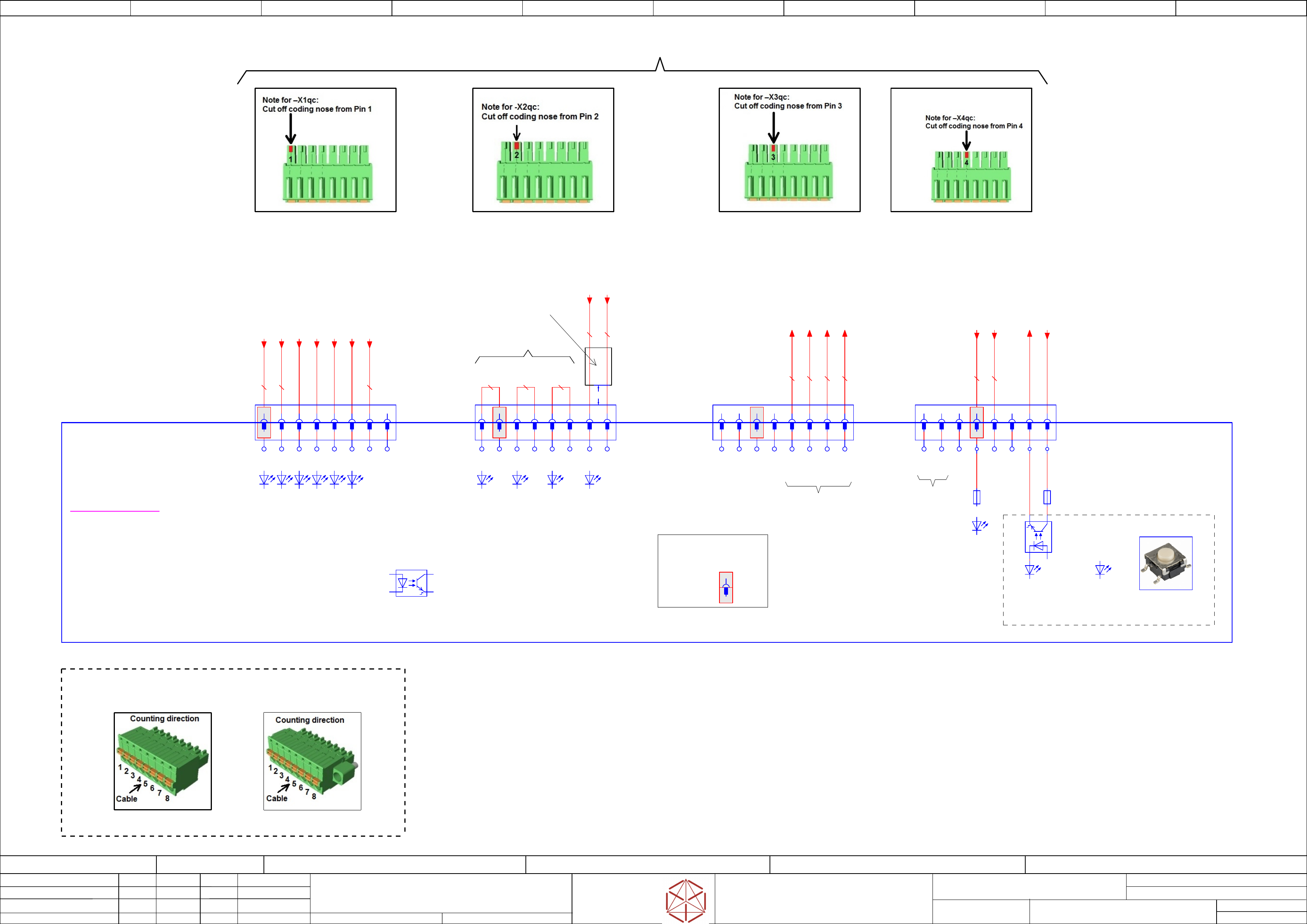
Safety signal converter
Replaced by
Weitergabe sowie Vervielfältigung dieser Unterlage, Verwertung und
Mitteilung des Inhalts nicht gestattet, soweit nicht ausdrücklich zugestanden.
Proprietary Data, company confidential.
All rights reserved
Copying of this document, giving it to others and the use or
communication of the contents thereof, are forbidden without express authority.
Doc. No.
0 1 2 3 4 5 6 7 8 9
Privileged business information.
Do not release
Offenders are liable to payment of damages. All rights are reserved in the
event of the grant or the registration of a utility model or design.
Zuwiederhandlungen verpflichten zu Schadenersatz. Alle Rechte vorbehalten,
insbesondere für den Fall der Patenterteilung oder GM-Eintragung vorbehalten.
Page:
Function: Distributor
==DI=SX12_V3+DI/49
drawing number:
03218436-030101LE3
Distributor_SX1(2)_V3
GmbH & Co KG
ASM
Assembly Systems
Copyright reserved
Ed.
Original
schnedlitz
Date
Date
Modification
Appr
30.04.2020
Name
starting MC-Nr.: 2018/Q3 G. Pingist
Size DIN A2
Sheet
49
/
3
"IN1-ON"
"IN2-ON"
"IN3-ON"
"IN4-ON"
"IN5-ON"
"IN6-ON"
To I/O-CU III
To I/O-CU III
- Foult detection circuit -
Manual test
of diagnosis function
-S1
"IN7-ON"
"IN8-ON"
"IN9-ON"
- not used -
Counting direction for Phoenix-Connector
FK-MCP 1,5/ 8-ST-3,81
1851106
FK-MCP 1,5/ 8-STF-3,81
1851290
Connector coding for -X1qc, -X2qc, -X3qc and -X4qc
)* )*)*
"IN10-ON"
)*
Note:
Coding profile is inserted
into the groove in the header:
-X1 (Pin 1)
-X2 (Pin 2)
-X3 (Pin 3)
-X4 (Pin 4)
)*
Heat shrink tubing (BK)
Length 30 mm ± 2
5 mm
Note:
Safety signal converter cpl. (03156919-xx)
is not part of the distributor (03152592-xx).
03156884-010201le3
-X4qc
MINI COMBICON FK-MCP 1,5/ 8-ST-3,81 8-pin
PXC.1851106
1 2 3 4 5 6 7 8
-X3qc
MINI COMBICON FK-MCP 1,5/ 8-ST-3,81 8-pin
PXC.1851106
1 2 3 4 5 6 7 8
-X1qc
MINI COMBICON FK-MCP 1,5/ 8-ST-3,81 8-pin
PXC.1851106
2 3 4 5 6 7 8
-X1
Safety Signal Inputs
1 2 3 4 5 6 7 8
-X3
to IOCU III
1 2 3 4 5 6 7 8
-X4
1 2 3 4 5 6 7 8
IN5
IN1
IN2
IN3
IN4
IN6
LGND
NC
S_OUT6
S_OUT10
S_OUT9
S_OUT8
S_OUT7
S_OUT5
S_OUT4
S_OUT3
GND-IN
S_OUT1
S_OUT2
NC
GND
-A2(qc)
Safety signal converter cpl.
03156919
Platine: - Not included in delivery -
Distributor
Safety signal converter PCBA
-H11
"PWR-ON"
-F1
0,12A
-H13
"OUTPUT-ON"
-H12
"FAIL/TEST"
all Inputs = optical coupler
+
+
-
-K1
Safety-Loop
IN/OUT
+
+-
-F2
0,12A
LOOP-IN
LOOP-OUT
P24V-IN
1,0 WH
1,0 WH
0,5 BK
0,5 BK
0,5 BK
0,5 BK
0,5 BK
0,5 BK
1,0 BN
-X2qc
MINI COMBICON FK-MCP 1,5/ 8-ST-3,81 8-pin
PXC.1851106
1 2 3 4 5 6
-X2
Safety Signal Inputs
1 2 3 4 5 6
IN9
IN7
P24
IN8
P24
P24
0,5 BK
0,5 BK
0,5 BK
7 8
IN10
IN10_GND
7 8
1,0 WH
0,5 BK
1
-Safety_Loop2_End
-qa-X9qa:1 /48.7
-24V_16b
-X1qa:16:b /48.2
-GND_12a
(IN1-9_GND)
-X1qa:12:a /48.1
-Safety_Loop1_X16
-qa-X16qa:4 ==CH/56.8
-Safety_Loop1_Begin.2
-qa-X9qa:3 /48.7
-EMG_STOP_Button_right_SSC
-qa-X8qa:4 ==CH/55.4
-DI12_EMG_Stop_Button_right
-X4qb:4 /48.4
-EMG_STOP_Button_left_SSC
-qa-X8qa:9 ==CH/55.5
-DI20_EMG_Stop_Button_left
-X5qb:4 /48.6
-Hood1_ServiceFlap1_SSC
-qa-X6qa:4 ==CH/54.6
-DI9_Hood1_serviceFlap1
-X4qb:7 /48.5
-Hood2_ServiceFlap2_SSC
-qa-X6qa:12 ==CH/54.7
-DI17_Hood2_serviceFlap2
-X5qb:7 /48.6
-GND_6d
-X1qa:6:d /48.1
-GND_4d
(IN10_GND)
-X1qa:4:d /48.0
-24V_19d
-X1qa:19:d /48.2
-24V_20a
-X1qa:20:a /48.3