ASM贴片机SX2机型电路图.pdf - 第56页
electric_schematic_SX12_V3 90013315-010101LE3 Replaced by Cable harness - fusing GCU1, GCU2, Trailing Interface-1 & 2 Replaced by Weitergabe sowie Vervielfältigung dieser Unterlage, Verwertung und Mitteilung des Inha…
electric_schematic_SX12_V3
90013315-010101LE3
Replaced by
Cable harness - fusing
Distributor, FCU1 FCU2, Conveyor
Replaced by
Weitergabe sowie Vervielfältigung dieser Unterlage, Verwertung und
Mitteilung des Inhalts nicht gestattet, soweit nicht ausdrücklich zugestanden.
Proprietary Data, company confidential.
All rights reserved
Copying of this document, giving it to others and the use or
communication of the contents thereof, are forbidden without express authority.
Doc. No.
0 1 2 3 4 5 6 7 8 9
Privileged business information.
Do not release
Offenders are liable to payment of damages. All rights are reserved in the
event of the grant or the registration of a utility model or design.
Zuwiederhandlungen verpflichten zu Schadenersatz. Alle Rechte vorbehalten,
insbesondere für den Fall der Patenterteilung oder GM-Eintragung vorbehalten.
Page:
Function: Cable Harness
==CH=SX12_V3+PS/51
drawing number:
03200800-010301LE3
Cable_harness SMPS
GmbH & Co KG
ASM
Assembly Systems
Copyright reserved
Ed.
Original
maettig
Date
Date
Modification
Appr
12.05.2020
Name
starting MC-Nr.: 2018/Q3 G. Pingist
Size DIN A2
Sheet
51
/
2
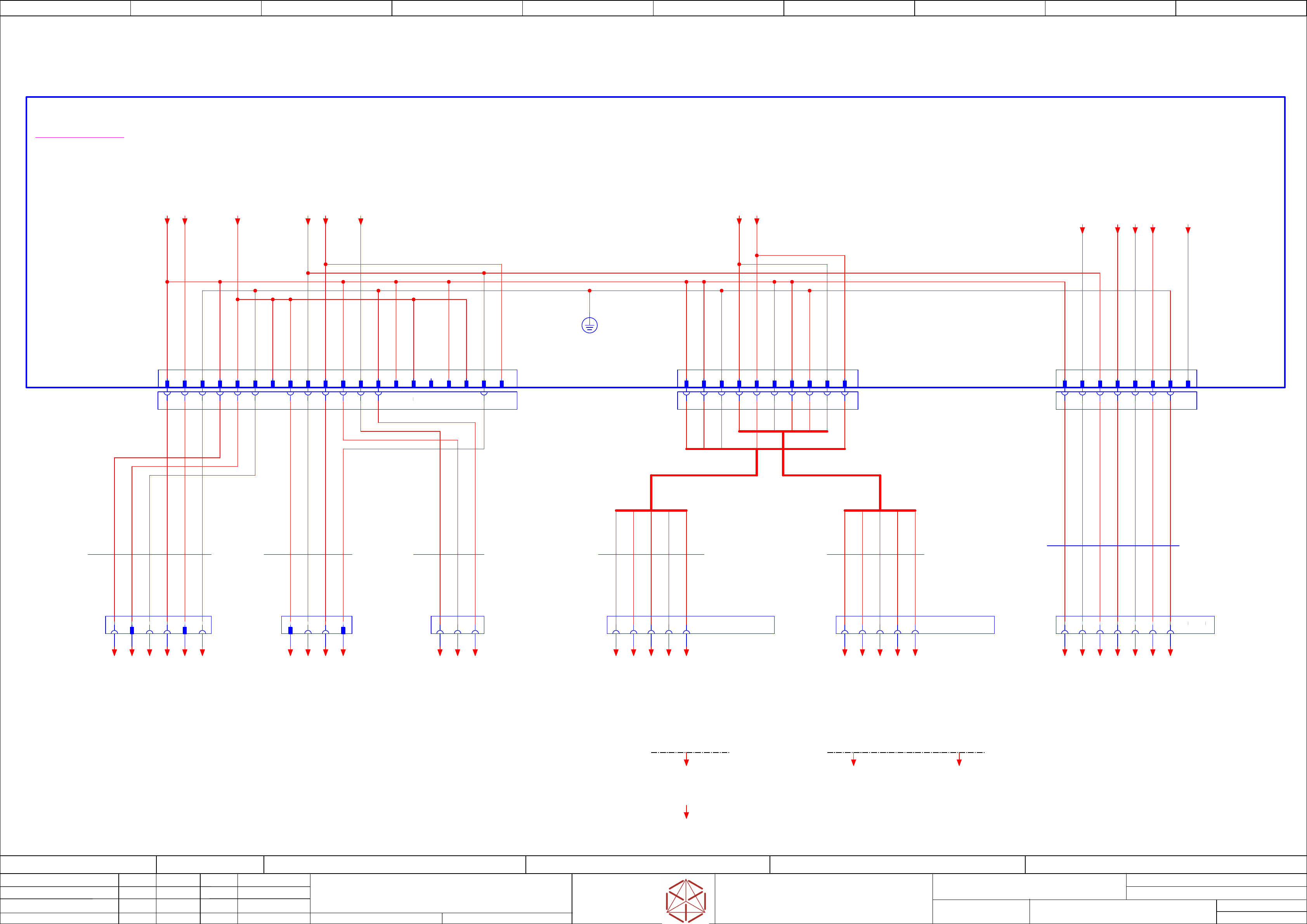
-X3qa
Distributor
2 51 3 4 6
Conveyor
-X79
Conveyor
1 2 3 4 5 6 7
8 9
B1 A4B3 B2B4A1 A5A3 A2B5
A1 B5A3A2
A4 B4B1 B2 B3
A5
03104070-020101le3
-XB2qy
A1 A2 A3 A4 A5 A6 A8 A9 A10 B1 B2 B3 B4 B5 B6 B7 B8 B9
B10
A7
-FD.A1
Fuse and distribution
-XB2
Power Distributor
& PC 3D-Sensor
A1
GND
A2
DC27V-PC1(F5)
A3
PE
A4
GND
A5
DC24V(F4)
A6
PE
A7
DC24V(F4)
A8
DC24V-Vision(F4)
A9
GND-42Vision
A10
DC42V-Vision(F21)
B1
GND-PC-opt
B2
DC27V-PC_opt(F6)
B3
PE
B4
GND
B5
DC24V(F4)
B6
NC
B7
GND
B8
DC24V(F4)
B9
GND-42Vision
B10
DC42V-Vision(F21)
-X1pb
Computer 3D sensor
1 2 3
-X2qa
Distributor
1 42 3
3170 mm
6x1,0
Single core
03068126
-W1.1
BK
BK
GNYE
BK
BK
GNYE
3120 mm
4x1,0
Single core
03068126
-W1.2
BK
BK
BK
BK
4380 mm
3x1,0
Single core
03068126
-W1.3
BK
BK
GNYE
-X111
FCU1 Power
Machine cable harness
to FCU 1
-X131
FCU2 Power
Machine cable harness
to FCU 2
2600 mm
5x2,5
Single Wire
03109616
-W9.1
3620 mm
5x2,5
Single Wire
03109616
-W9.2
BK
GNYE
6 6
1 2 3 4 51 2 3 4 5
7 8 97 8 9
-XB4qy
8
3160 mm
7x1,5
Single core
03068128
-W1
BK
BK
BK
BK
GNYE
BK
BK
1
GND
2
DC 24V (F7)
3
GND_42M
4
DC 42V_S (F16)
5
Power^31_ok (F10)
6
24V_S (F12)
7
PE
8
PWER_ENA
-XB4
Conveyor
54321 76
BK
BK
BK
BK
BK
BK
BK
GNYE
B5B4B3B2B1A5A4A3A2A1
-X5.FD
FCU 1&2
supply
-X5
FCU 1&2
DC 27V
B1
GND
B2
GND
B3
PE
A4
27V FCU2(F22)
B5
27V FCU2(F23)
A1
GND
A2
GND
A3
PE
B4
27V FCU2(F22)
A5
27V FCU2(F23)
-PE
==C3D+-24V(F6)_PC3D
==COP+Loc1/121.6
==C3D+-GND_PC3D
==COP+Loc1/121.6
==C3D+-PE_PC3D
==COP+Loc1/121.6
==DI+-24V(F4)_vision
==DI+DI/48.5
==DI+-GND1_vision
==DI+DI/48.5
==DI+-42V(F21)_vision
==DI+DI/48.5
==DI+-GND2_vision
==DI+DI/48.5
==DI+-27V(F5).2
==DI+DI/48.6
==DI+-PE.1
==DI+DI/48.6
==DI+-24V(F4).1
==DI+DI/48.6
==DI+-GND.1
==DI+DI/48.5
==DI+-PE.2
==DI+DI/48.6
==DI+-GND.2
==DI+DI/48.6
27V(F6)
==PS002+/44.2
27V(F5)
==PS002+/44.2
24V(F4)
==PS002+/44.3
==COTi60+Loc1-GND.1
==COTi60+Loc1/73.0
42V(F21)
==PS002+/44.1
==CO+-PWR_OK
==CO003+L1/112.1
==CO+-42V_S(F16)
==CO003+L1/112.1
==CO+-24V(F7)
==CO003+L1/112.1
==CO+-GND24
==CO003+L1/112.1
==CO+-24V(F12)_S
==CO003+L1/112.1
==CO+-GND42
==CO003+L1/112.1
==CO+-PE
==CO003+L1/112.2
24V(F7)
==PS002+/44.3
24V(F12)_S
==PS002+/44.9
42V(F16)_S
==PS002+/44.8
PWR_ENA
==PS002+/44.8
PWR_OK
==PS002+/44.2
GND42
==PS002+/44.4
GND27
==PS002+/44.4
==MT60=+Loc2-Power
alternative
Power_manual_table
==COTi30=+Loc2-Power
alternative
Power COTi30 + WPC
==MT60=+Loc1-Power
alternative
Power_manual_table
==COTi30=+Loc1-Power
==COTi30+Loc1_2/69.0
alternative
Power COTi30 + WPC
27V(F22)
==PS002+/44.2
27V(F23)
==PS002+/44.2
==COTi60+Loc1-27V(F23).1
==COTi60+Loc1/73.0
==COTi60+Loc1-GND.2
==COTi60+Loc1/73.0
==COTi60+Loc1-27V(F23).2
==COTi60+Loc1/73.0
==COTi60+Loc2-GND.1
==COTi60+Loc2/76.0
==COTi60+Loc2-27V(F22).1
==COTi60+Loc2/76.0
==COTi60+Loc2-GND.2
==COTi60+Loc2/76.0
==COTi60+Loc2-27V(F22).2
==COTi60+Loc2/76.0
==COTi60+Loc1-PE
==COTi60+Loc1/73.0
==COTi60+Loc2-PE
==COTi60+Loc2/76.0
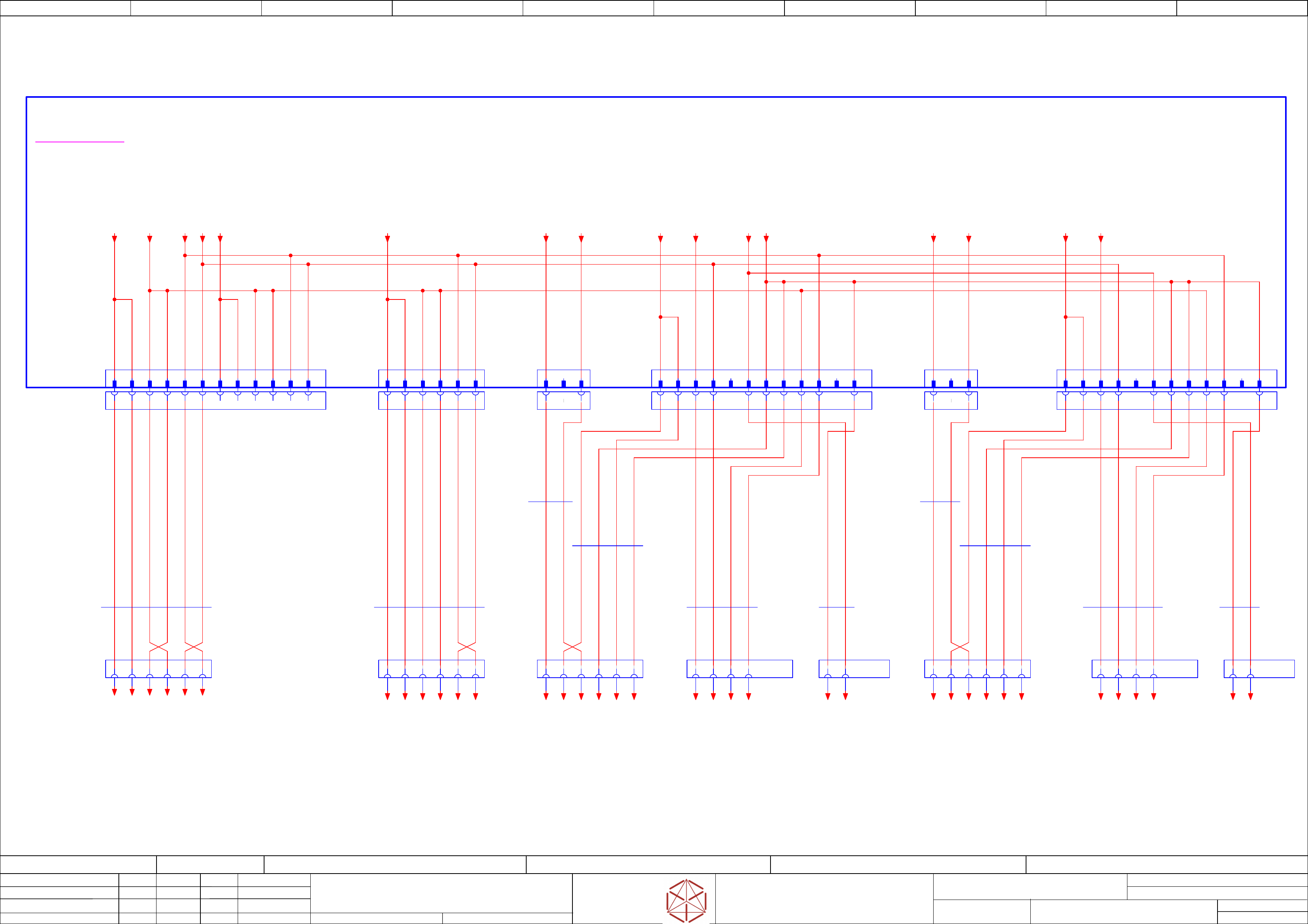
electric_schematic_SX12_V3
90013315-010101LE3
Replaced by
Cable harness - fusing
GCU1, GCU2, Trailing Interface-1 & 2
Replaced by
Weitergabe sowie Vervielfältigung dieser Unterlage, Verwertung und
Mitteilung des Inhalts nicht gestattet, soweit nicht ausdrücklich zugestanden.
Proprietary Data, company confidential.
All rights reserved
Copying of this document, giving it to others and the use or
communication of the contents thereof, are forbidden without express authority.
Doc. No.
0 1 2 3 4 5 6 7 8 9
Privileged business information.
Do not release
Offenders are liable to payment of damages. All rights are reserved in the
event of the grant or the registration of a utility model or design.
Zuwiederhandlungen verpflichten zu Schadenersatz. Alle Rechte vorbehalten,
insbesondere für den Fall der Patenterteilung oder GM-Eintragung vorbehalten.
Page:
Function: Cable Harness
==CH=SX12_V3+PS/52
drawing number:
03200800-010301LE3
Cable_harness SMPS
GmbH & Co KG
ASM
Assembly Systems
Copyright reserved
Ed.
Original
maettig
Date
Date
Modification
Appr
13.05.2020
Name
starting MC-Nr.: 2018/Q3 G. Pingist
Size DIN A2
Sheet
52
/
2
-X1sp
MGCU1
1 2 3 4 5 6
-XB1aqy
A1 A2 A3 A4 A6 B1 B2 B3 B4 B6A5 B5
-XB8aqy
1 32
-X15aa
Trailing Interface 1
1 2 3 4 5 6
-X13aa
Trailing Interface 1
1 2 3 4 5 6
-X14aa
Trailing Interface 1
1 2 3 4
-XB1bqy
A1 A2 A3 A4 A6 B1 B2 B3 B4 B6A5 B5
-X15ca
Trailing Interface 2
1 2 3 4 5 6
-X13ca
Trailing Interface 2
1 2 3 4 5 6
-X1up
MGCU2
1 2 3 4 5 6
-XB5aqy
A1 A2 A3 A4 A5 A6 B1 B2 B3 B4 B5 B6
03104070-020101le3
Attention!
All descriptions in this circuit diagram on cables,
boards and plugs with regard to GCU 3
refer to MGCU 2 with fuse F3!
-FD.A1
Fuse and distribution
-XB1a
Gantry-1
24V & Signals
A1
P 42 V (F14)
A2
P 42 V (F14)
A3
P 27 V (F8)
A4
Power_ok
A5
nc
B1
GND42
B2
GND42
B3
GND27
B4
PowerEnable (F10)
B5
nc
A6
P 42 V Vis (F21)
B6
GND_42
-XB5a
GCU1 GCU2 supply
B1
P 27 V GCU 2 (F2)
B2
P 27 V GCU 2 (F2)
A3
GND27
A4
GND27
A5
PowerEnable (F10)
A1
P 27 V GCU 1 (F1)
A2
P 27 V GCU 1 (F1)
B3
GND27
B4
GND27
B5
PowerEnable (F10)
A6
Power_ok (F10)
B6
Power_ok (F10)
4130 mm
2x1.5
ÖLFLEX® 150
03068132
-W1.1
4150 mm
4x0,75
Single core FLRY-A
03068132
-W1.3
BK
BK
BK
BK
4060 mm
2x0,75
Single core FLRY-A
03068132
-W1.4
BK
BK
4110 mm
4x0,75
Single core FLRY-A
03068132
-W1.2
BK
BK
BK
BK
2
1
-XB8bqy
1 32
-XB1b
Gantry-2
24V & Signals
A1
P 42 V (F15)
A2
P 42 V (F15)
A3
P 27 V (F9)
A4
Power_ok
A5
nc
B1
GND42
B2
GND42
B3
GND
B4
PowerEnable (F10)
B5
nc
A6
P 42 V Vis (F21)
B6
GND42
2180 mm
2x1.5
ÖLFLEX® 150
03068135
-W1.1
2250 mm
4x0,75
Single core FLRY-A
03068135
-W1.2
BK
BK
BK
BK
2200 mm
4x0,75
Single core FLRY-A
03068135
-W1.3
BK
BK
BK
BK
2120 mm
2x0,75
Single core FLRY-A
03068135
-W1.4
BK
BK
2
1
-X14ca
Trailing Interface 2
1 2 3 4
-XB8a
Gantry-1
DC160V
1
P160V_F19
2
nc
3
GND1_160V
-XB8b
Gantry-2
DC160V
1
P160V_F20
2
nc
3
GND2_160
-XB5b
GCU3 supply
1
P 27 V- GCU 3 (F3)
2
P 27 V GCU 3 (F3)
5
PowerEnable (F10)
6
Power_ok (F10)
3
GND27
4
GND27
-XB5bqy
1 2 3 4 5 6
2820 mm
6x1,0
Single core
03068134
-W1
BK
BK
BK
BK
BK
BK
4540 mm
6x1,0
Single core
03112207
-W1
BK
BK
BK
BK
BK
BK
==GCU1+-PWR_ENA_GCU1
+GA/62.1
==GCU1+-GND_GCU1.2
+GA/62.1
==GCU1+-24V(F1)_GCU1.2
+GA/62.0
==GCU1+-24V(F1)_GCU1.1
+GA/62.0
==GCU1+-GND_GCU1.1
+GA/62.0
==GCU1+-PWR_OK_GCU1
+GA/62.1
==TI+-P160V(F19)
+GA/63.2
==TI+-GND160.1
+GA/63.2
==TI+-P42V(F14)
+GA/63.2
==TI+-GND42.1
/52.4
==TI+-P42V(F14).1
+GA/63.3
==TI+-GND42.1
/52.4
==TI+-P27V(F8)
+GA/63.0
==TI+-PWR_OK.1
+GA/63.0
==TI+-GND27.1
+GA/63.0
==TI+-PWR_ENA.1
+GA/63.0
==TI+-GND_Vision.1
+GA/63.1
==TI+-42V_Vision.1
+GA/63.1
==TI+-P160V(F20)
+GA/65.2
==TI+-GND160.2
+GA/65.2
==TI+-P27V(F9)
+GA/65.0
==TI+-PWR_OK.2
+GA/65.0
==TI+-GND27.2
+GA/65.0
==TI+-PWR_ENA.2
+GA/65.0
==TI+-42V_Vision.2
+GA/65.1
==TI+-GND_Vision.2
+GA/65.1
==TI+-P42V(F15)
/52.7
==TI+-GND42.1
+GA/63.3
==TI+-P42V(F15)
/52.7
==TI+-GND42.2
+GA/65.3
P160V(F19)
==PS002+/44.7
GND160.1
==PS002+/44.7
P160V(F20)
==PS002+/44.8
GND160.2
==PS002+/44.8
42V(F14)
==PS002+/44.1
42V(F21)
==PS002+/44.1
27V(F8)
==PS002+/44.2
27V(F1)
==PS002+/44.1
27V(F2)
==PS002+/44.2
42V(F15)
==PS002+/44.1
27V(F9)
==PS002+/44.2
PWR_ENA
==PS002+/44.8
PWR_OK
==PS002+/44.2
GND27
==PS002+/44.4
GND42
==PS002+/44.4
27V(F3)
==PS002+/44.2
==GCU3+-PWR_ENA_GCU3
+GA/64.1
==GCU3+-GND_GCU3.1
+GA/64.0
==GCU3+-24V(F3)_GCU3.2
+GA/64.0
==GCU3+-24V(F3)_GCU3.1
+GA/64.0
==GCU3+-GND_GCU3.2
+GA/64.1
==GCU3+-PWR_OK_GCU3
+GA/64.1
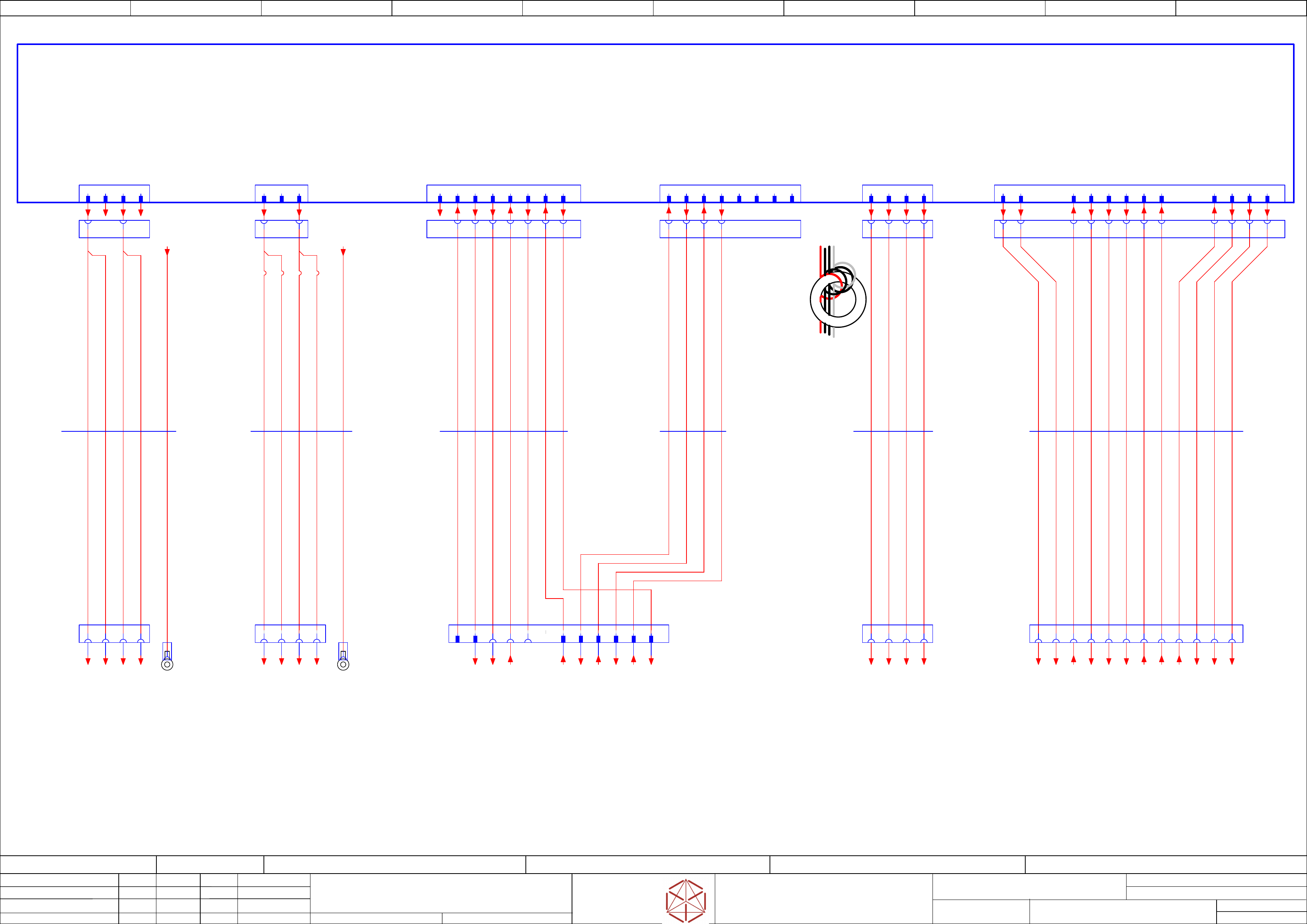
electric_schematic_SX12_V3
90013315-010101LE3
Replaced by
Cabling safety breaker to MGCU,
Distributor
Replaced by
Weitergabe sowie Vervielfältigung dieser Unterlage, Verwertung und
Mitteilung des Inhalts nicht gestattet, soweit nicht ausdrücklich zugestanden.
Proprietary Data, company confidential.
All rights reserved
Copying of this document, giving it to others and the use or
communication of the contents thereof, are forbidden without express authority.
Doc. No.
00 01 02 03 04 05 06 07 08 09
Privileged business information.
Do not release
Offenders are liable to payment of damages. All rights are reserved in the
event of the grant or the registration of a utility model or design.
Zuwiederhandlungen verpflichten zu Schadenersatz. Alle Rechte vorbehalten,
insbesondere für den Fall der Patenterteilung oder GM-Eintragung vorbehalten.
Page:
Function: Cable Harness
==CH=SX12_V3+CSB/53
drawing number:
03200800-010301LE3
Cable_harness Safety_breaker
GmbH & Co KG
ASM
Assembly Systems
Copyright reserved
Ed.
Original
schnedlitz
Date
Date
Modification
Appr
30.04.2020
Name
starting MC-Nr.: 2018/Q3 G. Pingist
Size DIN A2
Sheet
53
/
1
not
used
apply 3 windings
near X24A.CSB
use all wires
-X2up
MGCU2
1 2 3 4
-PE1
MGCU1-Frame
1 2 3 4
-X21
300V Power
-A2
Safety breaker unit
PCB Pre-/discharge assembly
03108631
-X22
300V Power
1 2
NC
3 A5A3B5
-X29
Safety Loop
& Signals
A6 A2A1 1 2 3 4 5 6 7 8
-X30
Safety
Loop extern
Star Voltage
-X24A.FD
Fuse and distribution
1 2 3 4
Control
-X24B.FD
Fuse and distribution
1 2 3 4 5 6 7 8 9 10 11 12
-X24A.CSB
Star Voltage
1 2 3 4
-X24B.CSB
Safety control
signals to FDB
DC42V IN/OUT
1 2 8 9 13 1475 6 10 15 16
1 32 4
-X24A
Safety
switched 160V
21
-X24B
Safety
control signals
42V IN/OUT
3 4 11 12
65 7 8 13 1514 169 10 11 123 4
550 mm
4x1,5
Single core
03110984
-W6.1
BK BK BK BK
550 mm
12x1,5
Single core
03110984
-W6.2
BK BK BK BK BK BK BK BK BK BK BK BK
B1B6
5290 mm
5G2,5
ÖLFLEX 150 UL
03112206
-W1
1
3
2
4
GNYE
-PE3
MGCU2-Frame
GNYE
3520 mm
5G2,5
ÖLFLEX 150 UL
03068133
-W1
3
2
4
1
-X21.CSB
MGCU1
-X2sp
1 2 3 4
1 3
-X22B.CSB
1 3
3650 mm
6x0,5
Single core UL/cUL Style
03200834
-W10.1
-X30.CSB
Safety
Loop Extern
1 2 3 4 5
-X29.CSB
Safety Loop
& Signals
extern
B5 A3 A5A1 A6 A2
3650 mm
4x0,5
Single core UL/cUL Style
03200834
-W10.2
6 7 8B1
YE YE YE YE YE YE YE YE YE YE
2 3 4 7 8 9 10 11 12
6
Safety-loop
& Signals
-X9qa
Distributor
51
YE
-GND300.1
==CSB+/47.01
-GND300.2
==CSB+/47.02
-DC300V.1
==CSB+/47.01
-DC300V.2
==CSB+/47.01
-GND300.3
==CSB+/47.04
-DC300V.3
==CSB+/47.03
-DC24V(F12)_S_DIS
==CSB+/47.08
-DI13_PWR_ENA
==CSB+/47.08
-DI0_Safety_Loop_OK
==CSB+/46.03
-SW_Control_ON
==CSB+/46.03
Safety_Start_SSK
-Safety_Loop1_Begin
==CSB+/46.03
-Safety_Loop1_End
==CSB+/46.04
-Safety_Loop1_ext.in
==CSB+/46.00
-Safety_Loop1_ext.out
==CSB+/46.00
-Safety_Loop2_ext.in
==CSB+/46.00
-Safety_Loop2_ext.out
==CSB+/46.01
-DC42V(F16)_S.1
==CSB+/47.05
-DC24V(F12)_S
==CSB+/47.07
-PWR_ENA
==CSB+/47.06
-DC42V(F16)_S.2
==CSB+/47.06
-24V(F12)
==CSB+/47.07
-24V(F11)
DC 24 V Safety supply
==CSB+/46.02
-GND.1
==CSB+/46.02
-DC160V_S.1
==CSB+/47.04
-DC160V_S.2
==CSB+/47.05
-GND160.1
==CSB+/47.05
-GND160.2
==CSB+/47.05
-CH1_OK
==CSB+/46.01
-CH2_OK
==CSB+/46.02
-42V(F16)-in-1
DC 42 V power supply
==CSB+/47.06
-42V(F16)-in-2
DC 42 V power supply
==CSB+/47.06
-PCC_PWR_OK
==CSB+/46.02
-42V(F16).1
==PS002+/44.08
-PWR_ENA
==PS002+/44.08
-42V(F16).2
==PS002+/44.09
-24V(F11)
==PS002+/44.08
-GND24
==PS002+/44.08
-DC160V_S.1
==PS002+/44.07
-DC160V_S.2
==PS002+/44.07
-GND160.1
==PS002+/44.07
-GND160.2
==PS002+/44.07
-42V(F16)_S.1
==PS002+/44.08
-42V(F16)_S.2
==PS002+/44.08
-PCC_PWR_OK
==PS002+/44.08
-24V(F12)_S
==PS002+/44.09
-24V(F12)
==PS002+/44.09
-CH1-OK
==PS002+/44.09
-CH2-OK
==PS002+/44.09
-Safety_Loop2_End
==CSB+/46.04
-Safety_Loop2_Begin
==CSB+/46.03
==GCU1+-DC300V.11
+GA/62.01
==GCU1+-GND300.11
+GA/62.02
==GCU1+-DC300V.12
+GA/62.01
==GCU3+-GND300.1
+GA/64.02
==GCU3+-DC300V.2
+GA/64.01
==GCU3+-DC300V.1
+GA/64.01
==GCU3+-GND300.2
+GA/64.02
==GCU1+-GND300.12
+GA/62.02
-PE_MGCU1
==PS002+/42.09
-PE_MGCU2
==PS002+/42.09
-SW_Control_ON
==DI+DI/48.07
-Safety_Loop_Begin
==DI+DI/48.07
-PCC43
==DI+DI/48.08
-DI13_PWR_ENA
==DI+DI/48.07
-Safety_Loop_End
-PCC53
==DI+DI/48.08
-PCC44
==DI+DI/48.08
-PCC54
==DI+DI/48.08
-24V(F12)_S_DI
==DI+DI/48.08