ASM贴片机SX2机型电路图.pdf - 第58页
electric_schematic_SX12_V3 90013315-010101LE3 Replaced by Cable harness distributor PC- Monitor- Gantry-voltage, Hood-1/2 Connector X4, X5, X6 Replaced by Weitergabe sowie Vervielfältigung dieser Unterlage, Verwertung un…
electric_schematic_SX12_V3
90013315-010101LE3
Replaced by
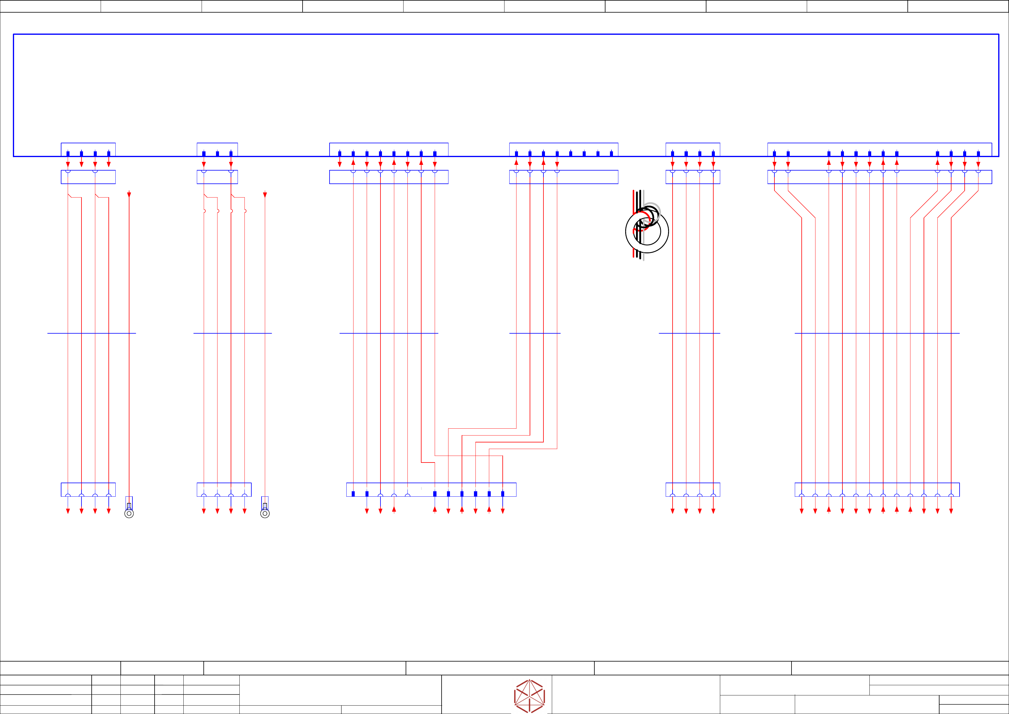
Cabling safety breaker to MGCU,
Distributor
Replaced by
Weitergabe sowie Vervielfältigung dieser Unterlage, Verwertung und
Mitteilung des Inhalts nicht gestattet, soweit nicht ausdrücklich zugestanden.
Proprietary Data, company confidential.
All rights reserved
Copying of this document, giving it to others and the use or
communication of the contents thereof, are forbidden without express authority.
Doc. No.
00 01 02 03 04 05 06 07 08 09
Privileged business information.
Do not release
Offenders are liable to payment of damages. All rights are reserved in the
event of the grant or the registration of a utility model or design.
Zuwiederhandlungen verpflichten zu Schadenersatz. Alle Rechte vorbehalten,
insbesondere für den Fall der Patenterteilung oder GM-Eintragung vorbehalten.
Page:
Function: Cable Harness
==CH=SX12_V3+CSB/53
drawing number:
03200800-010301LE3
Cable_harness Safety_breaker
GmbH & Co KG
ASM
Assembly Systems
Copyright reserved
Ed.
Original
schnedlitz
Date
Date
Modification
Appr
30.04.2020
Name
starting MC-Nr.: 2018/Q3 G. Pingist
Size DIN A2
Sheet
53
/
1
not
used
apply 3 windings
near X24A.CSB
use all wires
-X2up
MGCU2
1 2 3 4
-PE1
MGCU1-Frame
1 2 3 4
-X21
300V Power
-A2
Safety breaker unit
PCB Pre-/discharge assembly
03108631
-X22
300V Power
1 2
NC
3 A5A3B5
-X29
Safety Loop
& Signals
A6 A2A1 1 2 3 4 5 6 7 8
-X30
Safety
Loop extern
Star Voltage
-X24A.FD
Fuse and distribution
1 2 3 4
Control
-X24B.FD
Fuse and distribution
1 2 3 4 5 6 7 8 9 10 11 12
-X24A.CSB
Star Voltage
1 2 3 4
-X24B.CSB
Safety control
signals to FDB
DC42V IN/OUT
1 2 8 9 13 1475 6 10 15 16
1 32 4
-X24A
Safety
switched 160V
21
-X24B
Safety
control signals
42V IN/OUT
3 4 11 12
65 7 8 13 1514 169 10 11 123 4
550 mm
4x1,5
Single core
03110984
-W6.1
BK BK BK BK
550 mm
12x1,5
Single core
03110984
-W6.2
BK BK BK BK BK BK BK BK BK BK BK BK
B1B6
5290 mm
5G2,5
ÖLFLEX 150 UL
03112206
-W1
1
3
2
4
GNYE
-PE3
MGCU2-Frame
GNYE
3520 mm
5G2,5
ÖLFLEX 150 UL
03068133
-W1
3
2
4
1
-X21.CSB
MGCU1
-X2sp
1 2 3 4
1 3
-X22B.CSB
1 3
3650 mm
6x0,5
Single core UL/cUL Style
03200834
-W10.1
-X30.CSB
Safety
Loop Extern
1 2 3 4 5
-X29.CSB
Safety Loop
& Signals
extern
B5 A3 A5A1 A6 A2
3650 mm
4x0,5
Single core UL/cUL Style
03200834
-W10.2
6 7 8B1
YE YE YE YE YE YE YE YE YE YE
2 3 4 7 8 9 10 11 12
6
Safety-loop
& Signals
-X9qa
Distributor
51
YE
-GND300.1
==CSB+/47.01
-GND300.2
==CSB+/47.02
-DC300V.1
==CSB+/47.01
-DC300V.2
==CSB+/47.01
-GND300.3
==CSB+/47.04
-DC300V.3
==CSB+/47.03
-DC24V(F12)_S_DIS
==CSB+/47.08
-DI13_PWR_ENA
==CSB+/47.08
-DI0_Safety_Loop_OK
==CSB+/46.03
-SW_Control_ON
==CSB+/46.03
Safety_Start_SSK
-Safety_Loop1_Begin
==CSB+/46.03
-Safety_Loop1_End
==CSB+/46.04
-Safety_Loop1_ext.in
==CSB+/46.00
-Safety_Loop1_ext.out
==CSB+/46.00
-Safety_Loop2_ext.in
==CSB+/46.00
-Safety_Loop2_ext.out
==CSB+/46.01
-DC42V(F16)_S.1
==CSB+/47.05
-DC24V(F12)_S
==CSB+/47.07
-PWR_ENA
==CSB+/47.06
-DC42V(F16)_S.2
==CSB+/47.06
-24V(F12)
==CSB+/47.07
-24V(F11)
DC 24 V Safety supply
==CSB+/46.02
-GND.1
==CSB+/46.02
-DC160V_S.1
==CSB+/47.04
-DC160V_S.2
==CSB+/47.05
-GND160.1
==CSB+/47.05
-GND160.2
==CSB+/47.05
-CH1_OK
==CSB+/46.01
-CH2_OK
==CSB+/46.02
-42V(F16)-in-1
DC 42 V power supply
==CSB+/47.06
-42V(F16)-in-2
DC 42 V power supply
==CSB+/47.06
-PCC_PWR_OK
==CSB+/46.02
-42V(F16).1
==PS002+/44.08
-PWR_ENA
==PS002+/44.08
-42V(F16).2
==PS002+/44.09
-24V(F11)
==PS002+/44.08
-GND24
==PS002+/44.08
-DC160V_S.1
==PS002+/44.07
-DC160V_S.2
==PS002+/44.07
-GND160.1
==PS002+/44.07
-GND160.2
==PS002+/44.07
-42V(F16)_S.1
==PS002+/44.08
-42V(F16)_S.2
==PS002+/44.08
-PCC_PWR_OK
==PS002+/44.08
-24V(F12)_S
==PS002+/44.09
-24V(F12)
==PS002+/44.09
-CH1-OK
==PS002+/44.09
-CH2-OK
==PS002+/44.09
-Safety_Loop2_End
==CSB+/46.04
-Safety_Loop2_Begin
==CSB+/46.03
==GCU1+-DC300V.11
+GA/62.01
==GCU1+-GND300.11
+GA/62.02
==GCU1+-DC300V.12
+GA/62.01
==GCU3+-GND300.1
+GA/64.02
==GCU3+-DC300V.2
+GA/64.01
==GCU3+-DC300V.1
+GA/64.01
==GCU3+-GND300.2
+GA/64.02
==GCU1+-GND300.12
+GA/62.02
-PE_MGCU1
==PS002+/42.09
-PE_MGCU2
==PS002+/42.09
-SW_Control_ON
==DI+DI/48.07
-Safety_Loop_Begin
==DI+DI/48.07
-PCC43
==DI+DI/48.08
-DI13_PWR_ENA
==DI+DI/48.07
-Safety_Loop_End
-PCC53
==DI+DI/48.08
-PCC44
==DI+DI/48.08
-PCC54
==DI+DI/48.08
-24V(F12)_S_DI
==DI+DI/48.08
electric_schematic_SX12_V3
90013315-010101LE3
Replaced by
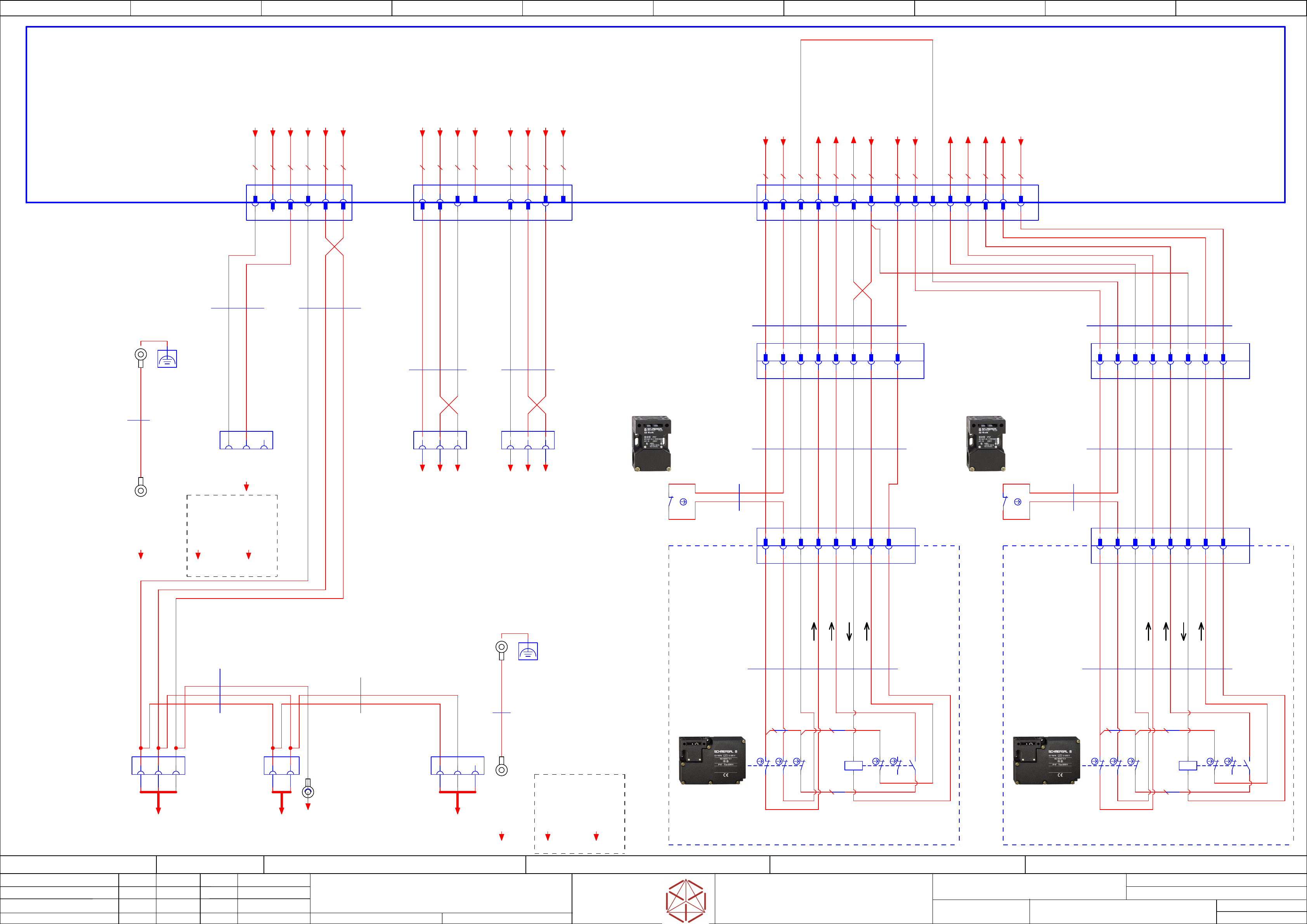
Cable harness distributor
PC- Monitor- Gantry-voltage, Hood-1/2
Connector X4, X5, X6
Replaced by
Weitergabe sowie Vervielfältigung dieser Unterlage, Verwertung und
Mitteilung des Inhalts nicht gestattet, soweit nicht ausdrücklich zugestanden.
Proprietary Data, company confidential.
All rights reserved
Copying of this document, giving it to others and the use or
communication of the contents thereof, are forbidden without express authority.
Doc. No.
00 01 02 03 04 05 06 07 08 09
Privileged business information.
Do not release
Offenders are liable to payment of damages. All rights are reserved in the
event of the grant or the registration of a utility model or design.
Zuwiederhandlungen verpflichten zu Schadenersatz. Alle Rechte vorbehalten,
insbesondere für den Fall der Patenterteilung oder GM-Eintragung vorbehalten.
Page:
Function: Cable Harness
==CH=SX12_V3+DI/54
drawing number:
03200800-010301LE3
Cable_harness Distributor
GmbH & Co KG
ASM
Assembly Systems
Copyright reserved
Ed.
Original
schnedlitz
Date
Date
Modification
Appr
30.04.2020
Name
starting MC-Nr.: 2018/Q3 G. Pingist
Size DIN A2
Sheet
54
/
4
Power 24V
Monitor-1
(12" monitor)
-X1.MON1
Solenoid interlock Solenoid interlock
-X4qa
2 3 5 61 4
-FRAME.MON2
Housing Monitor 2 (12")
M4
M6
Machine Frame
-FRAME.MF
Option 15" Monitor_1
Option 15" Monitor_1
1
3
2
1
2
1
3
2
-FRAME.MON1
Housing Monitor 1 (12")
M4
M6
Machine Frame
-FRAME.MF
Power
stationary
camera 1
-X4am
1 2 3 1 2 3
Power
stationary
camera 2
-X4bm
-X5qa
2 61 73 85
2540 mm
3x1,0
Single core
03200832
-W1.1
Cable: Power stationary
cameras
BK
BK
BK
3730 mm
3x1,0
Single core
03200832
-W1.2
Cable: Power stationary
cameras
BK
BK
BK
1 2 3 4 139 10 11 125 6 7 14 15
-X6qa
Extension hood 1
-X51
1 2 3 4 5 6 7 9
Extension hood 2
-X61
1 2 3 4 5 6 7 9
-X51.1
1 2 3 4 5 9
Extension hood 2
-X61.2
1 2 3 4 5 9
Extension hood 1
-X51.2
1 2 3 4 5 9
54321
-X61.1
9
1170 mm
8x0,75
Single core
03112121
-W1.1
Cable: Extension Hood
1 and 2
BK
BK
BK
BK
BK
BK
BK
4570 mm
8x0,75
Single core
03112121
-W1.2
Cable: Extension Hood 1
and 2
BK
BK
BK
BK
BK
BK
BK
100 mm
7x0,75
Single core
03112126
-1W1.1
BK
BK
BK
BK
100 mm
7x0,75
Single core
03112126
-2W1.1
Safety switch buffer
monitoring1_2
BK
BK
BK
BK
700 mm
2x0,75
UNITRONIC® LiYY A
03112126
-1W1.2
Safety switch buffer
monitoring1_2
WH
BN
-S2
Safety switch for
buffer monitoring-1_2
03078745
AZ15ZVK 1Oe
11
12
700 mm
2x0,75
UNITRONIC® LiYY A
03112126
-2W1.2
Safety switch buffer
monitoring1_2
WH
BN
-S1
Safety switch for
buffer monitoring-1_2
03078745
AZ15ZVK 1Oe
11
12
Location-1
Hood1
Solenoid interlock SX
03112130
-S1
AZM 161CC-12/03RKA-024
Drawn contact position: - Hood locked
- Bolt locked
11
12
21
22
41
42
51
52
71
72
63
64
locked /
not locked
A1
A2
/54.07
-X51
1
24V
2
Security Loop In
3
Security Loop Out
4
S_Hood 1
5
S_Hood 1 FCU
9
6
6
6
Hood 1_2_Lock
7
8
8
8
7
Hood 1_Lock_on
8
GND
7 8
530 mm
8x0,34
UNITRONIC® LiYY A
03112130
-1W1
Solenoid interlock
Hood1_2
6 7 8
6 7 8
8
BK
BK
BK BK
BK
BK
BK
BK
BK (J2) 0,33
50 mm
Bridge-J2
BK (J1) 0,33
50 mm
Bridge-J1
WH BN GN YE GY PK BU RD
Location-2
Hood2
Solenoid interlock SX
03112130
-S2
AZM 161CC-12/03RKA-024
Drawn contact position: - Hood locked
- Bolt locked
11
12
21
22
41
42
51
52
71
72
63
64
locked /
not locked
A1
A2
/54.09
1
24V
2
Security Loop In
3
Security Loop Out
4
S_Hood 2
5
S_Hood 2 FCU
96
Hood 1_2_Lock
7
Hood 2_Lock_on
8
GND
530 mm
8x0,34
UNITRONIC® LiYY A
03112130
-2W1
Solenoid interlock
Hood1_2
BK (J2) 0,33
50 mm
Bridge-J2
BK (J1) 0,33
50 mm
Bridge-J1
WH
-X61
BN GN YE GY PK BU RD
Bridge-J3
BK (J2) 0,33
50 mm
Bridge-J3
BK (J3) 0,33
50 mm
4 9
-X6qa
Hood-1/Hood-2
TYCO.172163-1
2 131251 9 10
-EMG_Loop1_X6
1143
-X5qa
Gantry voltages VLT33
TYCO.172161-1
73 41 2 6 8 95
-X4qa
24V Voltage CIN, PC
Monitor-1/2
TYCO.172160-1
41 2 5 63
-qa
Distributor unit SX1/2 V3
03218436
==PS002+VAC_P/45.01
1,0 BN
1,0 WH
1,0 GY
1,0 WH
1,0 BN
1,0 GY
1,0 WH
1,0 WH
1,0 BN
0,5 BK
0,5 BK
0,5 BK
0,5 BK
1,0 BN
0,5 BK
0,5 BK
0,5 BK
1,0 BN
1,0 WH
1,0 BN
1,0 WH
6
0,5 BK
14
0,5 BK
7
0,5 BK
8 15
1,0 WH
1,0 WH
1,0 BK
1,0 BK
1
24V
2
GND
3
Power 24V
Monitor-2
(12" monitor)
-X1.MON2
1
24V
2
GND
3
24V CIN
-POWER.CIN
1 2 3
-X80.PC
1 2
-PC.FG
BK 1,5
1300 mm
1x1,5
Single core MULTI-STANDARD SC 2.1
03233424
-W1.6
Cable: Power CIN, PC
and monitors
4000 mm
2x1,0
Single core
03233424
-W1.4
Cable: Power CIN, PC
and monitors
BK
BK
1150 mm
3x1,0
Single core
03233424
-W1.3
Cable: Power CIN, PC
and monitors
BK
BK
BK
4100 mm
3x1,0
Single core
03233424
-W1.2
Cable: Power CIN, PC
and monitors
BK BK BKBK BK
1580 mm
2x1,0
Single core
03233424
-W1.1
Cable: Power CIN, PC
and monitors
1800 mm
1x1,5
Single core MULTI-STANDARD SC 2.1
03233424
-W1.5
Cable: Power CIN, PC
and monitors
BK 1,5
==stCAM+-24V_vtl33_20c
==stCAM+Loc1/66.04
==stCAM+-GND_4c
==stCAM+Loc1/66.04
==stCAM+-42V_vtl33_21c
==stCAM+Loc1/66.04
==stCAM+-24V_vtl33_20d
==stCAM+Loc2/67.04
==stCAM+-GND_6c
==stCAM+Loc2/67.04
==stCAM+-42V_vtl33_21d
==stCAM+Loc2/67.04
-24V_PC1_13c
==DI-X1qa:13:c ==DI/48.02
-GND_2c
==DI-X1qa:2:c ==DI/48.00
-24V_PC1_13d
==DI-X1qa:13:d ==DI/48.02
-GND_3c
==DI-X1qa:3:c ==DI/48.00
-24V_vtl33_21c
==DI-X1qa:21:c ==DI/48.03
-GND_4c
==DI-X1qa:4:c ==DI/48.00
-42V_vtl33_22c
==DI-X1qa:22:c ==DI/48.03
-GND_5c
==DI-X1qa:5:c ==DI/48.00
-24V_vtl33_21d
==DI-X1qa:21:d ==DI/48.03
-GND_6c
==DI-X1qa:6:c ==DI/48.01
-42V_vtl33_22d
==DI-X1qa:22:d ==DI/48.03
-GND_7c
==DI-X1qa:7:c ==DI/48.01
-24V_15b
==DI-X1qa:15:b ==DI/48.02
-S_Hood1_FCU1
==DI-qa-X13qa:8 /56.01
-24V_15c
==DI-X1qa:15:c ==DI/48.02
-S_Hood2_FCU2
==DI-qa-X15qa:8 /56.06
-Safety_Loop_X8
(Loop_in)
==DI-qa-X8qa:8 /55.05
-DI13_Hood1_Lock_on
==DI-X4qb:3 ==DI/48.04
-DI21_Hood2_Lock_on
==DI-X5qb:3 ==DI/48.06
-GND_6a
==DI-X1qa:6:a ==DI/48.00
-GND_2d
==DI-X1qa:2:d ==DI/48.00
-DO7_Hood1_2_Lock
==DI-X7qb:1 ==DI/48.05
-FG_1d
==DI-X1qa:1:d ==DI/48.00
-FG_1c
==DI-X1qa:1:c ==DI/48.00
-Hood1_ServiceFlap1_SSC
==DI-X1qc:5 ==DI/49.02
-Hood2_ServiceFlap2_SSC
==DI-X1qc:6 ==DI/49.02
-Safety_Loop1_End
==DI-qa-X9qa:4 ==DI/48.07
[Monitor 2]
==+MON2-X1
+CTRL/58.08
-MON2_FRAME
+CTRL/58.08
[Monitor 1]
==+MON1-X1
+CTRL/58.01
[Control computer]
==+PC-POWER
+CTRL/58.00
[CAN Interface CIN]
==+CIN-POWER
+CTRL/58.09
[Monitor 1 (15″)]
==+MON_1-X1
+CTRL/59.01
-MON_1_FRAME
+CTRL/59.01
[Monitor 2 (15″)]
==+MON_2-X1
+CTRL/59.09
-MON_2_FRAME
+CTRL/59.08
-PC.FG
Housing M4
+CTRL/58.00
-MON1_FRAME
+CTRL/58.00
electric_schematic_SX12_V3
90013315-010101LE3
Replaced by
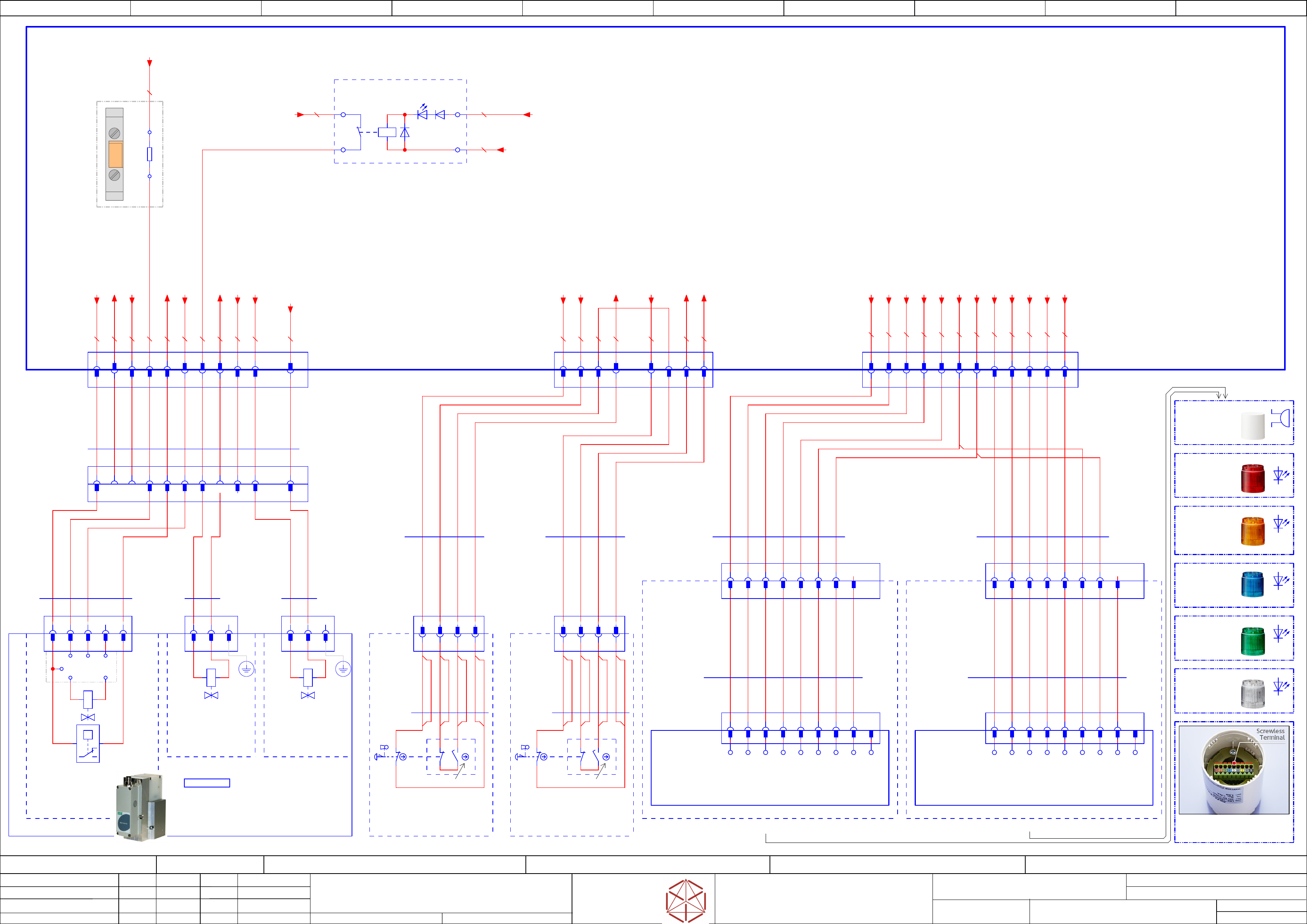
Cable harness distributor
Pneumatics, Conntrol-elements,
Fault-indicator
Connector X7, X8, X10
Replaced by
Weitergabe sowie Vervielfältigung dieser Unterlage, Verwertung und
Mitteilung des Inhalts nicht gestattet, soweit nicht ausdrücklich zugestanden.
Proprietary Data, company confidential.
All rights reserved
Copying of this document, giving it to others and the use or
communication of the contents thereof, are forbidden without express authority.
Doc. No.
00 01 02 03 04 05 06 07 08 09
Privileged business information.
Do not release
Offenders are liable to payment of damages. All rights are reserved in the
event of the grant or the registration of a utility model or design.
Zuwiederhandlungen verpflichten zu Schadenersatz. Alle Rechte vorbehalten,
insbesondere für den Fall der Patenterteilung oder GM-Eintragung vorbehalten.
Page:
Function: Cable Harness
==CH=SX12_V3+DI/55
drawing number:
03200800-010301LE3
Cable_harness Distributor
GmbH & Co KG
ASM
Assembly Systems
Copyright reserved
Ed.
Original
schnedlitz
Date
Date
Modification
Appr
30.04.2020
Name
starting MC-Nr.: 2018/Q3 G. Pingist
Size DIN A2
Sheet
55
/
4
-PF6.1(2)
LED unit LR5-E-RZ
50mm red clear
03162664
-PF4.1(2)
LED unit LR5-E-BZ
50mm blue clear
03162668
1 2 3 4 5 6 7 8 9 10 1211
-X60
1 2 3 4 6 7 8 95
-X8qa
-X52
1 2 3 4
-X7qa
1 2 3 4 6 7 8 95 10 1211
-X89
1 2 3
1 2
-X90
1 2 3
1 2
Control
9
9
9
Body unit LR5-02WTNW
03162662
1 2
A1
A211
12
WAGO 288-368
Relay module with 1 contact, nc
03002385
-K1
-X8qa
Conntrol_elements
Emergency_Stop_Button
64 7
-EMG_Loop_X8
8 951 2 3
-X62
1 2 3 4
-X60
4 6 7 95 10 122 3 8 11
-X90
1 2 3
-X89
1 2 3
-X91
1 3 5
-X62
1 2 3 4
-X52
1 2 3 4
3580 mm
11x0,75
Single core
03052264
-W1
BK
BK
BK
BK
BK
BK
BK
BK
BK
BK
BK
580 mm
2x0,5
UNITRONIC® LiYY A
03106361
-W1.1
BN
WH
580 mm
2x0,5
UNITRONIC® LiYY A
03106361
-W1.2
BN
WH
580 mm
4x0,34
UNITRONIC® LiYY A
03106361
-W1.3
YE
1720 mm
4x0,75
Single core
03052263
-W1.1
BK
BK
BK
BK
4750 mm
1x0,75
Single core
03052263
-W1.2
BK
BK
BK
BK
-S2
1NC
21
22
-S2
1NC
21
22
03173672
Emergency stop right
+CTRL_EMG_R
300 mm
8x0,34
UNITRONIC® LiYY A
03173672
-W1
GY
BU
WH
GN
03173672
Emergency stop left
+CTRL_EMG_L
300 mm
8x0,34
UNITRONIC® LiYY A
03173672
-W1
BN
YE
PK
RD
WH
GY
BU
GN
BN
YE
PK
RD
1
2 4
GN
WH
BN
-X91
1 2 3 4 5
-S1(PV1)
pressure_sensor
switches at 4,5bar
P
1 3
-Y_PV1
regulated-air
4,74bar
-Y_PV1
Proportional_valve_1
Sentronic-LP Serie 617
03152704
==OV+CH/12.00
-Y1
Main_pressure_valve
Valve-5/2 G1/8
03062277
==OV+CH/12.01
-Y2
Safety_valve
Valve-5/2 G1/4
00344974
==OV+CH/12.02
==FLUID+-U1
Pneumatic Group 1
03056289
==FLUID+/127.00
==OV+CH/12.00
==FLUID+/128.02
==FLUID+/129.01
V+ V-
24V
ANAin GND ANAout
12
-S1
1NC
with installation monitoring
11
12
-S1
1NC
with installation monitoring
11
03162662
Body unit LR5-02WTNW 50mm 24VDC
-UB1.1
-X1
1 2 3 5 6 7 8 9
Green
LED-G
Red
LED-R
Orange
LED-Y
Gray
Buzzer
Blue
LED-B
White
LED-C
Gray
Flashing
Yellow
Power wire
Black
Power wire
600 mm
8x0,23
UNITRONIC® LiYY A
03209094
-W1
Connection cable signal
tower LR5 series
4
-X1.FIL
TYCO.172161-1
Mini MATE-N-LOK
Socket 9-pin
Terminal block body unit
-X1
1
red
2
orange
3
green
4
blue
5
white
6
gray
7
yellow
8
gray
1 3 4 5 62 7 8
YE
WH
RD
GY
GN
PK
BU
BN
03162662
Body unit LR5-02WTNW 50mm 24VDC
-UB2.1
-X1
1 2 3 4 5 6 7 8 9
Green
LED-G
Red
LED-R
Orange
LED-Y
Gray
Buzzer
Blue
LED-B
White
LED-C
Gray
Flashing
Yellow
Power wire
Black
Power wire
600 mm
8x0,23
UNITRONIC® LiYY A
03209094
-W1
Connection cable signal
tower LR5 series
YE
WH
RD
GY
GN
PK
BU
-X1.FIL
TYCO.172161-1
Mini MATE-N-LOK
Socket 9-pin
Terminal block body unit
-X1
1
red
2
orange
3
green
4
blue
5
white
6
gray
7
yellow
8
gray
1 3 4 5 62 7 8
BN
Buzzer
white
green
yellow
-PF5.1(2)
LED unit LR5-E-YZ
50mm yellow clear
03162665
red
-PJ1.1(2)
Buzzer unit LR5-BW
50mm
03162667
-PF2.1(2)
LED unit LR5-E-CZ
50mm white clear
03162666
-PF3.1(2)
LED unit LR5-E-GZ
50mm green clear
03162663
blue
-UB1
Distributor
DI
(Basis module
and connection cable)
Signal tower 1
-UB2
Distributor
DI
(Basis module
and connection cable)
Signal tower 2
1 2 5 6 743
128 9 10 11
-X1.FIL1
Mini MATE-N-LOK Plug 9-pin
2 3 4 651 7
8 9
-X1.FIL2
Mini MATE-N-LOK Plug 9-pin
2 3 4 651 7
8 9
BK
4800 mm
x0,5
Single core
03200833
-W1.2
Fault indicator lamp
Cable: Ext. fault indicator lamp 1 and 2
BK
BK
BK
BK
BK
BK
BK
BK
BK
BK
BK
BK
BK
-X10qa
2010 mm
x0,5
Single core
03200833
-W1.1
Fault indicator lamp
Cable: Ext. fault indicator lamp 1 and 2
-X7qa
Pneumatic
Main_System
1 4
-Commpressed_Air_OFF_Controller_Valve
5 9 10 122 3 6 7
Main Valve
8 11
-qa
Distributor unit SX1/2 V3
03218436
==PS002+VAC_P/45.01
0,5 BK
1,0 OG
1,0 WH
1,0 WH
1,0 WH
0,5 BK
0,5 BK
0,5 BK
1,0 WH
0,5 BK
0,5 BK
1,0 WH
0,5 BK
1,0 OG
1,0 OG
0,5 BK
0,5 BK
0,5 BK
0,5 BK
1,0 WH
1,0 OG
0,5 BK
Terminal-clamp
with Resistor 15K
-X1
2
-X1
1
-R1
15K
-X10qa
Fault_indicator_lamp
4 5 8 9 10 11 121 2 3 6 7
1,0 WH
0,5 BK
0,5 BK
0,5 BK
0,5 BK
0,5 BK
0,5 BK
0,5 BK
0,5 BK
0,5 BK
0,5 BK
0,5 BK
-GND_3d
==DI-X1qa:3:d ==DI/48.00
-DO5_Compressed_Air_Main_valve
==DI-X7qb:3 ==DI/48.06
-24V_16c
==DI-X1qa:16:c ==DI/48.02
-DO3_Compressed_Air_Ctrl_valve
==DI-X7qb:5 ==DI/48.06
-DI6_X7qa_reserve
/
==DI/48.03 / -X3qb:2
-DI2_Vacuum_OK
==DI-X3qb:6 ==DI/48.03
-DI15_PresSensorMainValve
==DI-X4qb:1 ==DI/48.04
-GND_8b
==DI-X1qa:8:b ==DI/48.01
-GND_8a
==DI-X1qa:8:a ==DI/48.01
-GND_7a
==DI-X1qa:7:a ==DI/48.01
-24V_15d
==DI-X1qa:15:d ==DI/48.02
-GND_7b
==DI-X1qa:7:b ==DI/48.01
-24V_16d
==DI-X1qa:16:d ==DI/48.02
-24V_17b
==DI-X1qa:17:b ==DI/48.02
-Safety_Loop_X8
(Loop_out)
==DI-qa-X6qa:2 /54.05
-24V(F12)_S_23c
Safety Valve
==DI-X1qa:23:c ==DI/48.03
-GND_5d
==DI-X1qa:5:d ==DI/48.00
-DO8_RD_Indicator_1_(Right)
==DI-X8qb:8 ==DI/48.08
-DO9_YE_Indicator_1_(Right)
==DI-X8qb:7 ==DI/48.08
-DO11_GN_Indicator_1_(Right)
==DI-X8qb:5 ==DI/48.07
-DO10_BU_Indicator_1_(Right)
==DI-X8qb:6 ==DI/48.07
-DO12_WH_Indicator_1_(Right)
==DI-X8qb:4 ==DI/48.07
-D23_Buzzer_1/2
==DI-X17qb:1 ==DI/48.08
-DO16_RD_Indicator_2_(Left)
==DI-X17qb:8 ==DI/48.09
-DO17_YE_Indicator_2_(Left)
==DI-X17qb:7 ==DI/48.09
-DO18_BU_Indicator_2_(Left)
==DI-X17qb:6 ==DI/48.09
-DO19_GN_Indicator_2_(Left)
==DI-X17qb:5 ==DI/48.09
-DO20_WH_Indicator_2_(Left)
==DI-X17qb:4 ==DI/48.09
-Safety_Loop1_X16_2
-IN
==DI-qa-X16qa:4 /56.08
-EMG_STOP_Button_right_SSC
==DI-X1qc:3 ==DI/49.02
-EMG_STOP_Button_left_SSC
==DI-X1qc:4 ==DI/49.02