ASM贴片机SX2机型电路图.pdf - 第90页
electric_schematic_SX12_V3 90013315-010101LE3 Replaced by SPS (Smart Pin Support)_G1 Replaced by Weitergabe sowie Vervielfältigung dieser Unterlage, Verwertung und Mitteilung des Inhalts nicht gestattet, soweit nicht aus…
electric_schematic_SX12_V3
90013315-010101LE3
Replaced by
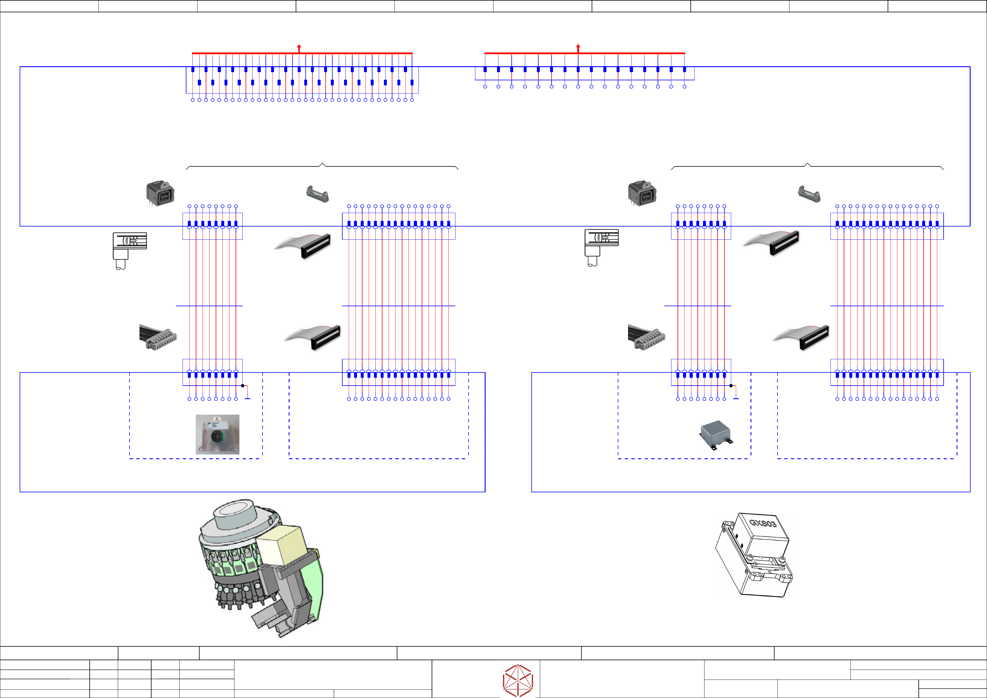
Gantry1_Vision Head Interface & Cameras
Replaced by
Weitergabe sowie Vervielfältigung dieser Unterlage, Verwertung und
Mitteilung des Inhalts nicht gestattet, soweit nicht ausdrücklich zugestanden.
Proprietary Data, company confidential.
All rights reserved
Copying of this document, giving it to others and the use or
communication of the contents thereof, are forbidden without express authority.
Doc. No.
0 1 2 3 4 5 6 7 8 9
Privileged business information.
Do not release
Offenders are liable to payment of damages. All rights are reserved in the
event of the grant or the registration of a utility model or design.
Zuwiederhandlungen verpflichten zu Schadenersatz. Alle Rechte vorbehalten,
insbesondere für den Fall der Patenterteilung oder GM-Eintragung vorbehalten.
Page:
Function: Gantry
==GA=SX12_V3+GA1/85
drawing number:
Gantry
GmbH & Co KG
ASM
Assembly Systems
Copyright reserved
Ed.
Original
Schnedlitz
Date
Date
Modification
Appr
12.12.2019
Name
starting MC-Nr.: 2018/Q3 G. Pingist
Size DIN A2
Sheet
85
/
4
3
4
5
6
7
8
9
10
11
12
13
14
15
16
17
18
19
20
21
22
23
24
25
26
27
28
29
30
31
32
33
34
2
1
-X.J11
2 4 6 8 10 12 14 16 18 20 22 24 26 28 30 323 5 7 9 11 13 15 19 21 23 25 27 29 31 331 3417 1 162 3 4 5 6 7 9 10 11 12 138 14 14
PCB-Camera (CAM 2)Component-Camera (CAM 1)
Component
camera (Type 48)
8x8 GigE
Placement Head
SpeedStar (C&P20 P2)
PCB - Camera
(Type 34)
28 GigE
-X1
1
2
3
4
5
6
7
8
9
10
11
12
13
14
15
16
GND
+42V
MCAN_RX
GND
MCAN_TX_
PORTAL-ID0
+24V
HCU-TRIG_
+42V
GND
MCAN_RX_
MCAN_TX
GND
PORTAL-ID1
HCU-TRIG
GND
Component camera C+P (Type 48) 8x8 GigE
PCB camera (Type 34) 28 GigE
Gantry 1
-au
Vision Head Interface VHI
03100949
TX_N_2
GND_CAM_2
DATA1_P_2
CLK_N_2
GND_CAM_2
DATA2_P_2
GND_CAM_2
TX_P_2
DATA1_N_2
GND_CAM_2
CLK_P_2
DATA2_N_2
GND_CAM_2
Shield
P42V_BEL_2
P42V_BEL_2
POWERFAIL_N_2
NC
GND1_2
GCAN_H_2
MCAN_H_2
P12V_CAM_2
GND_CAM_2
RX_P_2
P42V_BEL_2
P42V_BEL_2
GND
GND
PIN10_2
GCAN_L_2
MCAN_L_2
GND2_2
P12V_CAM_2
RX_N_2
1 2 3 4 5 6 7 8 9 1110 12
PORTAL_ID0
P42V
IN_GND
TRIGGER_HCU_P
TRIGGER_HCU_N
PORTAL_ID1
IN_24V
MCAN_L
13 14
MCAN_H
-X.J5
15 16
P42V
P42V
IN_GND
IN_GND
IN_GND
IN_GND
IN_GND
CAM 2
-X.J1
SAMTEC_EHF-108-01-L-D-SM-LC
1
2
3
4
5
6
7
8
9
10
11
12
13
14
15
16
C3_GND
C3_RXP
P40V
C3_GND
P40V
C3_RXN
C3_TXP
C3_TXN
C3_GND
C3_GND
C3_ID0
C3_24V
C3_HCUP
C3_ID1
C3_HCUN
C3_GND
CAM 2
-X.J16
HRS_GT17VB-8DP-DS-SB
1
2
3
4
5
6
7
8
MX2-
MX3+
MX1-
MX1+
MX2+
MX3-
MX4-
MX4+
CAM 1
-X.J9
SAMTEC_EHF-108-01-L-D-SM-LC
1
2
3
4
5
6
7
8
9
10
11
12
13
14
15
16
C3_GND
C3_RXP
P40V
C3_GND
P40V
C3_RXN
C3_TXP
C3_TXN
C3_GND
C3_GND
C3_ID0
C3_24V
C3_HCUP
C3_ID1
C3_HCUN
C3_GND
CAM 1
-X.J14
HRS_GT17VB-8DP-DS-SB
1
2
3
4
5
6
7
8
MX2-
MX3+
MX1-
MX1+
MX2+
MX3-
MX4-
MX4+
2 4 6 81 3 5 7
-X1
03101676
GXS50 GigE CMOS
5Mpix Kamera
BAUMER
-CAM1
03131695
Gantry 1
Component Camera C+P
(Type 48) 8x8 GigE
-Co_Cam
03146613
PCBA
Vision LED controller
VLC48 GigE
-A1
MX1+
MX2+
MX3+
MX4+
MX1-
MX2-
MX3-
MX4-
SHIELD
-X9.VHI
1
2
3
4
5
6
7
8
9
10
11
12
13
14
15
16
-X1.VLC
1
2
3
4
5
6
7
8
9
10
11
12
13
14
15
16
7531 8642
-X14.VHI
7531 8642
-X1.CAM
435 mm
4x2x0,09
CAT5 cable
03112087
-1W1
Cable: Camera type 41 GigE
BU/WH
BU
OG
OG/WH
GN/WH
GN
BN
BN/WH
405 mm
16x0,05
Flat round cable
03112088
-1W1
Cable VHI - VLC41 GigE
1
2
3
4
5
6
7
8
9
10
11
12
13
14
15
16
-X1
1
2
3
4
5
6
7
8
9
10
11
12
13
14
15
16
GND
+42V
MCAN_RX
GND
MCAN_TX_
PORTAL-ID0
+24V
HCU-TRIG_
+42V
GND
MCAN_RX_
MCAN_TX
GND
PORTAL-ID1
HCU-TRIG
GND
-X1.VHI
1
2
3
4
5
6
7
8
9
10
11
12
13
14
15
16
-X1.VLC
1
2
3
4
5
6
7
8
9
10
11
12
13
14
15
16
03100758
PCBA
Vision LED controller
VLC34 GigE
-A2
520 mm
16x0,05
Flat round cable
03097629
-2W1
Cable VHI - VLC34 GigE
1
2
3
4
5
6
7
8
9
10
11
12
13
14
15
16
03101402
Gantry 1
PCB camera
(Type 34) 28 GigE
-PCB_Cam
2 4 6 81 3 5 7
-X1
7531 8642
-X16.VHI
7531 8642
-X1.CAM
03101431
GXS03 GigE
CCD VGA camera
BAUMER
-CAM2
MX1+
MX2+
MX3+
MX4+
MX1-
MX2-
MX3-
MX4-
SHIELD
530 mm
4x2x0,09
CAT5 cable
03090967
-2W1
Cable Camera Type 34 GigE
BU/WH
BU
OG
OG/WH
GN/WH
GN
BN
BN/WH
==GA1+-X.J5au
/84.8
VHI-Board
==GA1+-X.J11au
/83.8
Trailing_cable_X4 (GigE)__GigE
electric_schematic_SX12_V3
90013315-010101LE3
Replaced by
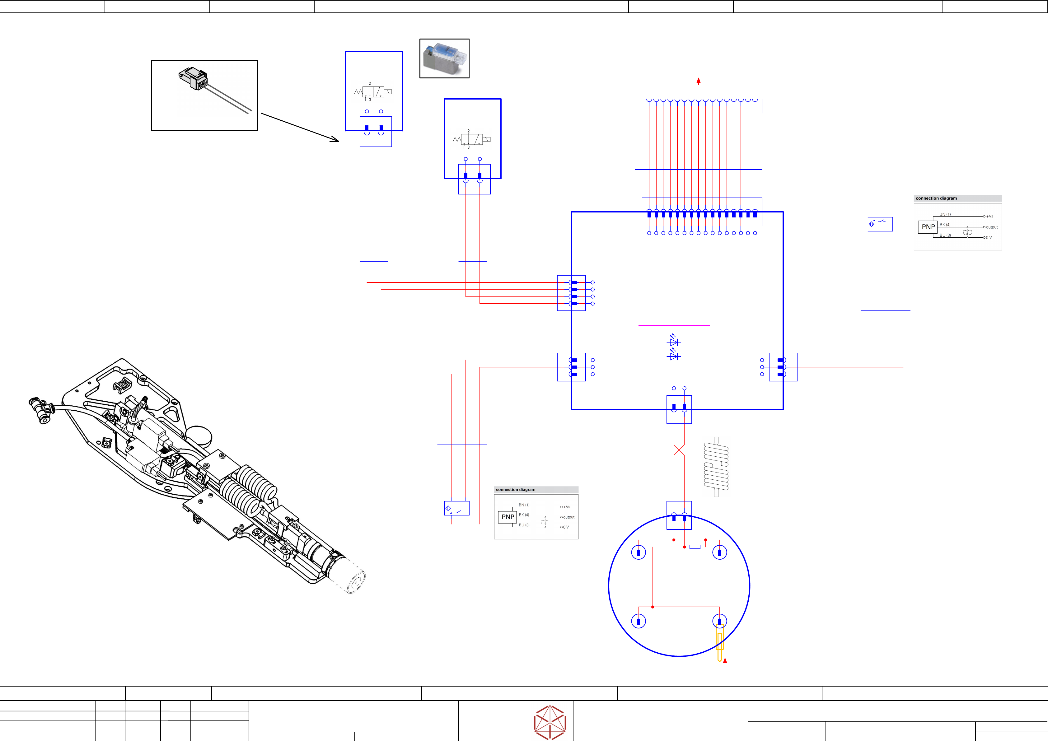
SPS (Smart Pin Support)_G1
Replaced by
Weitergabe sowie Vervielfältigung dieser Unterlage, Verwertung und
Mitteilung des Inhalts nicht gestattet, soweit nicht ausdrücklich zugestanden.
Proprietary Data, company confidential.
All rights reserved
Copying of this document, giving it to others and the use or
communication of the contents thereof, are forbidden without express authority.
Doc. No.
00 01 02 03 04 05 06 07 08 09
Privileged business information.
Do not release
Offenders are liable to payment of damages. All rights are reserved in the
event of the grant or the registration of a utility model or design.
Zuwiederhandlungen verpflichten zu Schadenersatz. Alle Rechte vorbehalten,
insbesondere für den Fall der Patenterteilung oder GM-Eintragung vorbehalten.
Page:
Function: Smart Pin Support
==SPS=SX12_V3/132
drawing number:
03089621-030301LE3
Gantry 1
GmbH & Co KG
ASM
Assembly Systems
Copyright reserved
Ed.
Original
schnedlitz
Date
Date
Modification
Appr
14.05.2020
Name
starting MC-Nr.: 2018/Q3 G. Pingist
Size DIN A2
Sheet
132
/
1
Spiral cable
expand = 120mm
SPS-Valve
-Valve1
3/2-way-
magnet valve
03085498
(-) (+)
-X2
-Valve2
3/2-way-
magnet valve
03085498
(-) (+)
-X3
1 2
-X1
Option
Smart Pin Support (SPS) - Pin Picker SX1/2
00119992
Connector X2 and X3 with contacts SY100
without cable (03090303-xx)
SMC
Valve connector
-X3
(-) (+)
-X2
(-) (+)
Magnet Valve1 and 2
V114A-5MOU
03089614-020101le3
stroke
4x
Spring_contact_probe
F702 (d=1,3mm)
03087957
SPS Pin Picker SX1/2 _ 03089622-xx
Gantry 1
-X8
SPS
GND
GND
GND
GND
GND
CAN_TX_XC
Portal_ID1
Portal_IO_LR
CAN_RX_XC
1 3 5 7 92 4 6 8
-Cont
PCBA
Control board SPS
Portal_ID0
10
GND
11
15V+
12
24V+
13
24V+
14
24V+
24V+
15 16
-Grip
PCBA
Contact gripper
cpl. SPS
03090306
U_PIN_2
U_PIN_1
1 2
-X5
1 2
-X5
1 2
-X1
165 mm
03091099 -01
-W1
Spiral cable
gripper
1 2
1
2
Inductive
sensor "bottom"
-X6
GND
Input
3
24V+_Sicherung
-B1
Inductive
proximity
switch
"bottom"
IFFM 08P37A6/L
1
+Vs
4
output
3
0V
+ -
3
2
1
Inductive
sensor "top"
-X7
GND
24V+_Sicherung
Input
1
2
SPS-Valve
-X9
0V
24V
3
0V
4
24V
1
2
3
4
-X1(9)
1
2
3
-X6(7)
120 mm
03093273 -01
-W1
Cable:
Inductive
proximity switch "top"
BKBN BU
BKBN BU
200 mm
03090192 -01
-W1
Cable:
Inductive
proximity switch "bottom"
-X3
Spring
contact
-X2
Spring
contact
-X4
Spring
contact
-X5
Spring
contact
107 mm
2x0,14
Single core
03088170-01
-W1.2
Cable: SPS-Valve
BK3 BK4
130 mm
2x0,14
Single core
03088170-01
-W1.1
Cable: SPS-Valve
BK1 BK2
1
2
3
-X6
1
+Vs
4
output
3
0V
-B2
Inductive
proximity
switch
"top"
+ -
_
+
-R1
100K
-V16
GREEN
Sensor botton
-V17
GREEN
Sensor top
-X1
1 2 3 4 6 8 10 12 14 165 7 9 11 13 15
-X8
1 3 5 7 9 11 13 152 4 6 8 10 12 14 16
450 mm
20x0.05
Flat round cable
03090966
-W1
1
2
3
4
5
6
7
8
9
10
11
12
13
14
15
16
==GA1=+-SPS
Option Smart_Pin_Support
==GA+GA1/84.04
electric_schematic_SX12_V3
90013315-010101LE3
Replaced by
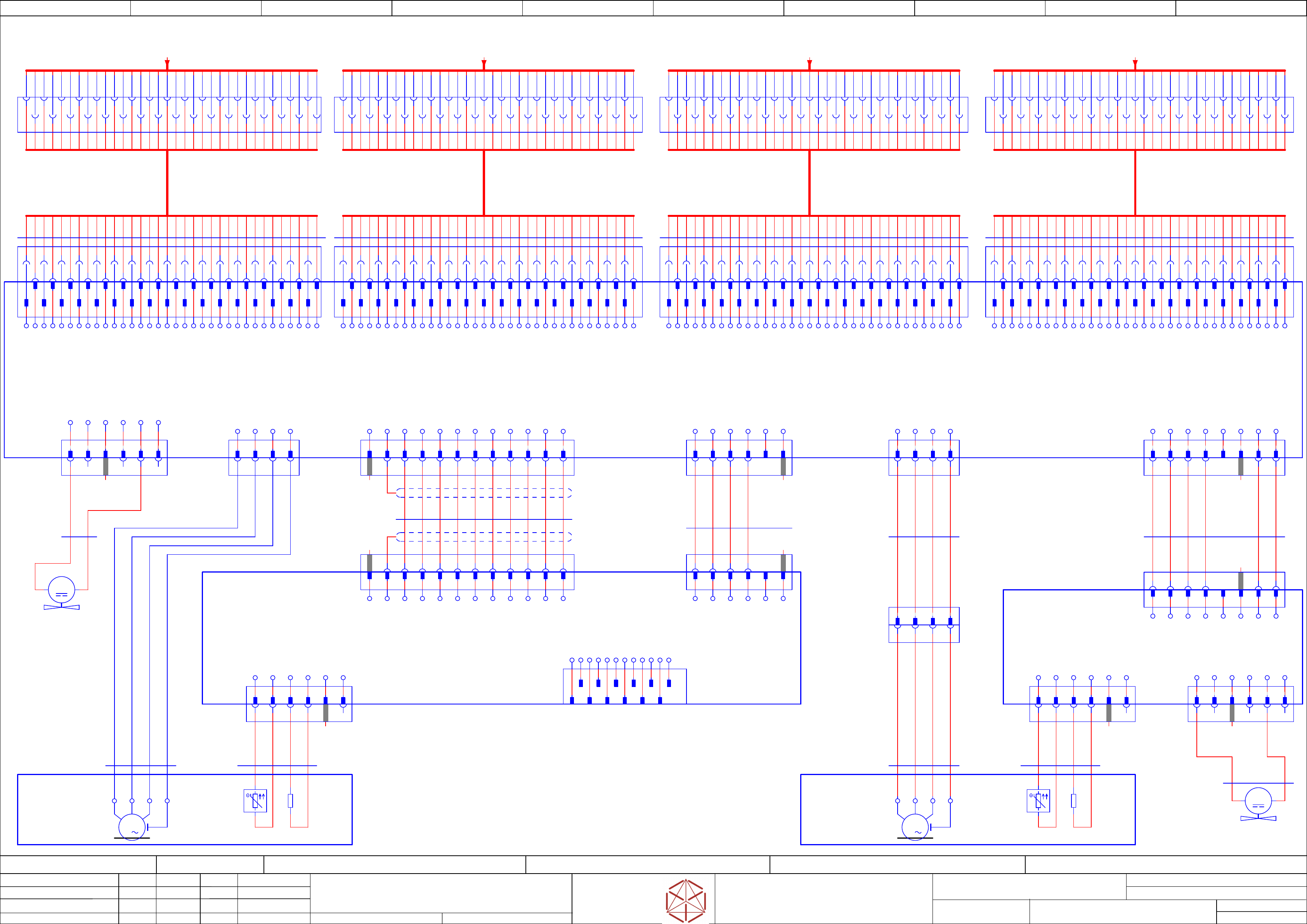
Gantry2_Motor_Y
Replaced by
Weitergabe sowie Vervielfältigung dieser Unterlage, Verwertung und
Mitteilung des Inhalts nicht gestattet, soweit nicht ausdrücklich zugestanden.
Proprietary Data, company confidential.
All rights reserved
Copying of this document, giving it to others and the use or
communication of the contents thereof, are forbidden without express authority.
Doc. No.
0 1 2 3 4 5 6 7 8 9
Privileged business information.
Do not release
Offenders are liable to payment of damages. All rights are reserved in the
event of the grant or the registration of a utility model or design.
Zuwiederhandlungen verpflichten zu Schadenersatz. Alle Rechte vorbehalten,
insbesondere für den Fall der Patenterteilung oder GM-Eintragung vorbehalten.
Page:
Function: Gantry
==GA=SX12_V3+GA2/86
drawing number:
Gantry
GmbH & Co KG
ASM
Assembly Systems
Copyright reserved
Ed.
Original
maettig
Date
Date
Modification
Appr
12.05.2020
Name
starting MC-Nr.: 2018/Q3 G. Pingist
Size DIN A2
Sheet
86
/
5
12
-MY1
Fan Y1 motor
03085456
M
Key
1
21
-MY2
Fan Y2 motor
03085456
M
6
Key
Key
6
Key
5
Key
5
Key
6
Key
W V U PE
-MY1
3
M
U V W PE
-MY2
3
M
Motor protection Motor protection
Gantry 2
2 4 6 8 10 12 14 16 18 20 22 24 26 28 30 323 5 7 9 11 13 15 19 21 23 25 27 29 31 331 3417 2 4 6 8 10 12 14 16 18 20 22 24 26 28 30 323 5 7 9 11 13 15 19 21 23 25 27 29 31 331 3417
3
4
5
6
7
8
9
10
11
12
13
14
15
16
17
18
19
20
21
22
23
24
25
26
27
28
29
30
31
32
33
34
2
1
-X3
Trailing cable Y3
Motor Y2
1
3
5
7
9
11
13
15
17
19
21
23
25
27
29
31
33
2
4
6
8
10
12
14
16
18
20
22
24
26
28
30
34
-X3ca
32
1
3
5
7
9
11
13
15
17
19
21
23
25
27
29
31
33
2
4
6
8
10
12
14
16
18
20
22
24
26
28
30
32
34
-X4ca
20
18
16
14
12
10
8
6
4
2
19
17
15
13
11
9
7
5
3
1
21
22
23
24
25
26
27
28
29
30
31
32
33
34
-X3cq
2 4 6 8 10 12 14 16 18 20 22 24 26 28 30 323 5 7 9 11 13 15 19 21 23 25 27 29 31 331 3417
3
4
5
6
7
8
9
10
11
12
13
14
15
16
17
18
19
20
21
22
23
24
25
26
27
28
29
30
31
32
33
34
2
1
-X2
Trailing cable Y2
Motor Y1
1
3
5
7
9
11
13
15
17
19
21
23
25
27
29
31
33
2
4
6
8
10
12
14
16
18
20
22
24
26
28
30
34
-X2ca
32
20
18
16
14
12
10
8
6
4
2
19
17
15
13
11
9
7
5
3
1
21
22
23
24
25
26
27
28
29
30
31
32
33
34
-X2cq
2 4 6 8 10 12 14 16 18 20 22 24 26 28 30 323 5 7 9 11 13 15 19 21 23 25 27 29 31 331 3417
1 2 3 4
-X5
Motor/Power
Y1-Axis
2
4
6
8
10
12
14
16
18
20
22
24
26
28
30
32
3
5
7
9
11
13
15
19
21
23
25
27
29
31
33
1
34
17
2
4
6
8
10
12
14
16
18
20
22
24
26
28
30
32
3
5
7
9
11
13
15
19
21
23
25
27
29
31
33
1
34
17
2
4
6
8
10
12
14
16
18
20
22
24
26
28
30
32
3
5
7
9
11
13
15
19
21
23
25
27
29
31
33
1
34
17
2
4
6
8
10
12
14
16
18
20
22
24
26
28
30
32
3
5
7
9
11
13
15
19
21
23
25
27
29
31
33
1
34
17
3
5
7
9
11
13
15
19
21
23
25
27
29
31
33
2
4
6
8
10
12
14
16
18
20
22
24
26
28
30
32
1
34
17
3
5
7
9
11
13
15
19
21
23
25
27
29
31
33
2
4
6
8
10
12
14
16
18
20
22
24
26
28
30
32
1
34
17
3
5
7
9
11
13
15
19
21
23
25
27
29
31
33
2
4
6
8
10
12
14
16
18
20
22
24
26
28
30
32
1
34
17
3
5
7
9
11
13
15
19
21
23
25
27
29
31
33
2
4
6
8
10
12
14
16
18
20
22
24
26
28
30
32
1
34
17
1 2 3 4 5 6 7 8 9 1110 12
-X7
Sensor module
Y axis
Achtung! Der Body für
TSW-106-25-L-D-RA-012 (X7)
hat SAMTEC Zählweise,
d.h. PIN12 = KEY;
im Stromlauf von 2007
ist das PIN1 !!!
Achtung!
Der Body für
TSW-104-25-L-D-RA-003 (X8)
hat SAMTEC Zählweise,
d.h. PIN3 = KEY;
im Stromlauf von 2007
ist das PIN6 !!!
Key
3
1
Key
Key
3
6
-X10cq
1 2 4 5 6
420 mm
2x0,2
UL1007
03085456-01
-1W1
RD
BK
590 mm
4x1
TP Chainflex CF10.UL.10.04
03092337-01
-W1.1
-cb
Sensor module Y axis
03064608
-cr
Sensor interface
03060962
==OV+GA/25.2
-X7cq
2 3 4 5 6 7 8 9 10 11 12
1 2 3 4 5 6 7 8 9 1110 12
-X21
-X21cb
2 3 4 5 6 7 8 9 10 11 12
-X9cq
1 2 3 4
5
X11_TEMP_PTC_1
X11_TEMP_PTC_2
X11_TEMP_ADC_1
X11_TEMP_ADC_2
NC
KEY
-X11
Temp
1 2 3 4 5 6
-X31
Debug-connector
A1 A2 A3 A4 A5 A6
B1
1 2 3 4 5 6
-X12
-X12cb
1 2 3 4
5
L3
L2
L1
GNYE
-X8cq
1 2 3 4 7 8
-X6cq
1 2 3 4
Key
FDB_SMY_GCU_CH4_OUT_P
FDB_SMY_GCU_CH4_OUT_N
FDB_SMY_GCU_CH3_OUT_P
FDB_SMY_GCU_CH3_OUT_N
FDB_SMY_GCU_CH1_OUT_P
FDB_SMY_GCU_CH1_OUT_N
FDB_SMY_GCU_CH2_IN_P
FDB_SMY_GCU_CH2_IN_N
PE
GND
P24V
-X2
1 2 3 4
300 mm
5x2x0,23
UNITRONIC LiYCY (TP) UL/CSA
03052148 -02
-W1
X12_TEMP_PTC_1
X12_TEMP_PTC_2
X12_TEMP_ADC_1
X12_TEMP_ADC_2
NC
KEY
-X1
Temp & fan
1 2 3 4 5 6 7 8
-X1cr
1 2 3 4 7 8
X12_TEMP_PTC_1
X12_TEMP_PTC_2
X12_TEMP_ADC_1
X12_TEMP_ADC_2
NC
KEY
-X3
FAN Y2 Motor
1 2 4 5 6
-X3cr
1 2 4 5 6
KEY
3
P40V_FAN
NC
GND
NC
NC
420 mm
2x0,2
UL1007
03085456
-01
-2W1
BK
RD
590 mm
4x1
TP Chainflex CF10.UL.10.04
03092337-01
-W1.1
L1
L2
L3
GNYE
-X6cq2
1 2 3 4
-X2
1 2 3 4
570 mm
4x0,34
UNITONIC LiYY
03052145 -01
-W1
SH
SH
BN
GN
YE
WH
810 mm
4G1,5
ÖLFLEX 150 CY QUATTRO
03052146 -01
-W1
1
2
3
GNYE
X31_FPGA_TDI
X31_FPGA_TDO
P3V3
FDB_SMY_DU_CH1_OUT_P
GND
GND
GND
GND
GND
FDB_SMY_DU_CH1_OUT_N
X31_FPGA_TMS
X31_FPGA_TCK
B2 B3 B4 B5 B6
800 mm
7x0,34
UNITRONIC LiYCY UL/CSA
03052147-03
-W1
WH
BN
GN
YE
GY
PK
5
5
-X2
Temp
1 3 4 6
-X1
1 3
5
6
2
2 4
-X1
1 3 62 4
BN
GN
YE
GY
PK
BU
RD
BK
VT
WH
X12_TEMP_PTC_1
X12_TEMP_PTC_2
X12_TEMP_ADC_1
X12_TEMP_ADC_2
KEY
NC
P40V_FAN
GND
-MY1
Linear motor
Y1 axis
03092337
Phase W
Phase U
Phase V
GND
-PT100
+
-
660 mm
4xAWG22
Unitronic 300
03092337-01
-W1.2
RD
BN
BK
OR
-MY2
Linear motor
Y2 axis
03092337
Phase 1
Phase 3
Phase 2
GND
-PT100
+
-
660 mm
4xAWG22
Unitronic 300
03092337-01
-W1.2
RD
BN
BK
OR
-PTC130
3x PTC
(series connection)
-PTC130
3x PTC
(series connection)
3
4
5
6
7
8
9
10
11
12
13
14
15
16
17
18
19
20
21
22
23
24
25
26
27
28
29
30
31
32
33
34
2
1
-X4
Trailing cable Y4
Motor Y2
20
18
16
14
12
10
8
6
4
2
19
17
15
13
11
9
7
5
3
1
21
22
23
24
25
26
27
28
29
30
31
32
33
34
-X4cq
-cq
Gantry-Interface Y SX1/2 (GigE)
03215037
2077 mm
34x0,14
Flat rib. cable
03204803
-W1
Trailing_cable_Y3_(GigE)
Y2_Motor
2073 mm
34x0,14
Flat rib. cable
03204804
-W1
Trailing_cable_Y4_(GigE)
Y2_Motor
2080 mm
34x0,14
Flat rib. cable
03204802
-W1
Trailing_cable_Y2_(GigE)
Y1_Motor
3
4
5
6
7
8
9
10
11
12
13
14
15
16
17
18
19
20
21
22
23
24
25
26
27
28
29
30
31
32
33
34
2
1
-X1
Trailing cable Y1
Motor Y1
1
3
5
7
9
11
13
15
17
19
21
23
25
27
29
31
33
2
4
6
8
10
12
14
16
18
20
22
24
26
28
30
34
-X1ca
32
20
18
16
14
12
10
8
6
4
2
19
17
15
13
11
9
7
5
3
1
21
22
23
24
25
26
27
28
29
30
31
32
33
34
-X1cq
2083 mm
34x0,14
Flat rib. cable
03204801
-W1
Trailing-cable_Y 1_(GigE)
Y1_Motor
SCREEN
Y1_MOTOR_U
Y1_MOTOR_U
Y1_MOTOR_U
Y1_MOTOR_V
Y1_MOTOR_V
Y1_MOTOR_V
Y1_MOTOR_W
Y1_MOTOR_W
Y1_MOTOR_W
SCREEN
Y1TEMPSENS
Y1TRACKNN/FDB_EPM_CH9_BUS_N
GND
Y1TRACKB/FDB_EPM_CH6_BUS_P
Y1TRACKAN/FDB_EPM_CH5_BUS_N
GND
SCREEN
Y1_MOTOR_U
Y1_MOTOR_U
Y1_MOTOR_U
Y1_MOTOR_V
Y1_MOTOR_V
Y1_MOTOR_V
Y1_MOTOR_W
Y1_MOTOR_W
Y1_MOTOR_W
SCREEN
GND_CAN_RELAY
Y1TRACKNN/FDB_EPM_CH9_BUS_P
Y1TRACKBN/FDB_EPM_CH6_BUS_N
GND
Y1TRACKA/FDB_EPM_CH5_BUS_P
SCREEN
Y1_AXIS_ERROR_24V_N
GND
P27V
GND
GND
P27V
SCREEN
P42V_FAN
GND
GND
P27V
GND
SCREEN
SCREEN
Y1_MOTOR_U
Y1_MOTOR_U
Y1_MOTOR_U
Y1_MOTOR_V
Y1_MOTOR_V
Y1_MOTOR_V
Y1_MOTOR_W
Y1_MOTOR_W
Y1_MOTOR_W
SCREEN
SCREEN
Y1_MOTOR_U
Y1_MOTOR_U
Y1_MOTOR_U
Y1_MOTOR_V
Y1_MOTOR_V
Y1_MOTOR_V
Y1_MOTOR_W
Y1_MOTOR_W
Y1_MOTOR_W
Y2TEMPSENS
Y2TRACKNN/FDB_EPM_CH10_BUS_N
GND
Y2TRACKB/FDB_EPM_CH8_BUS_P
Y2TRACKAN/FDB_EPM_CH7_BUS_N
GND
SCREEN
GND_CAN_RELAY
Y2TRACKN/FDB_EPM_CH10_BUS_P
Y2TRACKBN/FDB_EPM_CH8_BUS_N
GND
Y2TRACKA/FDB_EPM_CH7_BUS_P
SCREEN
SCREEN
Y2_MOTOR_U
Y2_MOTOR_U
Y2_MOTOR_U
Y2_MOTOR_V
Y2_MOTOR_V
Y2_MOTOR_V
Y2_MOTOR_W
Y2_MOTOR_W
Y2_MOTOR_W
SCREEN
SCREEN
Y2_MOTOR_U
Y2_MOTOR_U
Y2_MOTOR_U
Y2_MOTOR_V
Y2_MOTOR_V
Y2_MOTOR_V
Y2_MOTOR_W
Y2_MOTOR_W
Y2_MOTOR_W
Y2_AXIS_ERROR_24V_N
GND
P27V
GND
GND
P27V
SCREEN
P42_FAN
GND
GND
P27V
GND
SCREEN
SCREEN
Y2_MOTOR_U
Y2_MOTOR_U
Y2_MOTOR_U
Y2_MOTOR_V
Y2_MOTOR_V
Y2_MOTOR_V
Y2_MOTOR_W
Y2_MOTOR_W
Y2_MOTOR_W
SCREEN
SCREEN
Y2_MOTOR_U
Y2_MOTOR_U
Y2_MOTOR_U
Y2_MOTOR_V
Y2_MOTOR_V
Y2_MOTOR_V
Y2_MOTOR_W
Y2_MOTOR_W
Y2_MOTOR_W
-X10
FAN X/Y Motor
1 2 4 5 6
KEY
3
P42V_FAN
NC
GND
NC
NC
Y1_MOTOR_W
Y1_MOTOR_V
Y1_MOTOR_U
SCREEN
-X8
Temp & fan
-X6
Motor/Power
Y2-Axis
Y1TRACKAN/FDB_EPM_CH5_BUS_N
Y1TRACKA/FDB_EPM_CH5_BUS_P
Y1TRACKBN/FDB_EPM_CH6_BUS_N
Y1TRACKB/FDB_EPM_CH6_BUS_P
Y2TRACKAN/FDB_EPM_CH7_BUS_N
Y2TRACKA/FDB_EPM_CH7_BUS_P
Y2TRACKBN/FDB_EPM_CH8_BUS_N
Y2TRACKB/FDB_EPM_CH8_BUS_P
SCREEN
KEY
1 2 3 4 5 6
-X9
Temp.
sensor
X12_TEMP_PTC_1
X12_TEMP_PTC_2
X12_TEMP_ADC_1
X12_TEMP_ADC_2
NC
KEY
GND
P27V
1 2 3 4 5 6 7 81 2 3 4
GND
P42V_FAN
KEY
NC
X12_TEMP_ADC_2
X12_TEMP_ADC_1
X12_TEMP_PTC_2
X12_TEMP_PTC_1
Y!_MOTOR_W
Y1_MOTOR_V
Y1_MOTOR_U
SCREEN
==GA2+-X4ca
==CH+GA/64.8
Trailing cable Y4 (GigE) - Motor Y2
03204804-W1
==GA2+-X3ca
==CH+GA/64.6
Trailing cable Y3 (GigE) - Motor Y2
03204803-W1
==GA2+-X2ca
==CH+GA/64.3
Trailing cable Y2 (GigE) - Motor Y1
03204802-W1
==GA2+-X1ca
==CH+GA/64.1
Trailing cable Y1 (GigE) - Motor Y1
03204801-W1