00194313-03 - 第53页
SIPLACE S-25 HM / S-27 HM 2 Assembly Inst ructions for PCB Camera, Multicolor 02/2007 Edition 2.3 Safety Instructions 53 2.3 Safety Instructions DANGER Only Siemens service engine ers are permitted to perform the assembl…
2 Assembly Instructions for PCB Camera, Multicolor SIPLACE S-25 HM / S-27 HM
2.2 Requirements 02/2007 Edition
52
– To assembly the modular head boards, relatively old S-23 machines that have been upgraded
to S-25 HM (Retro) require 3 new 10-pin connectors and 1 new 16-pin connector that have to
be fitted on the existing ribbon cables (see Abb. 2.6.10 and Assembly Instructions "Head PCB,
modular....."). This is necessary to effect the strain relief for the cables.
The Service Center is keeping these parts on hand in a separate package, along with the ne-
cessary special tools (see Section 2.4.2.1).
S-27 HM 2
– Software version: 503.01 or later
2
2
SIPLACE S-25 HM / S-27 HM 2 Assembly Instructions for PCB Camera, Multicolor
02/2007 Edition 2.3 Safety Instructions
53
2.3 Safety Instructions
DANGER
Only Siemens service engineers are permitted to perform the assembly of the "PCB camera Mul-
ticolor". Comply with the higher ranking "Safety Instructions" in Chapter "Operational Safety" in
the User Manual and Service Manual.
The machines SIPLACE are powered by line voltage.
Portions of the system are therefore conducting dangerous electricity, inside the machine even
while the master switch is turned off.
After you have properly carried out the shut-down of the operating system:
Before all work the machine must be turned off at the main switch and isolated from the mains. In
addition, the compressed air supply must be turned off at the main valve of the compressed air
unit in the machine base and the compressed air lines must be bled by actuating the needle valve
at the compressed air unit (particularly due to the risk of injury - posed by residual air - at the pneu-
matic cutter after undocking/removing the component changeover table).
Obey the applicable accident prevention regulations, DIN standards and special safety codes of
your country at all times. DIN EN 60204 must be adhered to during all work inside the machine
base.
Follow the instructions regarding residual voltages in Chapter "Operational Safety".
Comply with regulations on ESDs (see Chapter "Operational Safety").
During the work of assembly secure the machine conscientiously against other personnel and pre-
vent it from being turned back on without authorization, as described in the User Manual in the
chapter "Locking the Machine...".
There is additional, higher risk of accident when working with the SITEST program.
The SITEST program is only to be started by personnel who are authorized to do so.
For the work with the SITEST program the component changeover table must be moved in and
correctly connected. 2
2
2
2
2
2
2
2
2 Assembly Instructions for PCB Camera, Multicolor SIPLACE S-25 HM / S-27 HM
2.3 Safety Instructions 02/2007 Edition
54
2.3.1 Safety Notes about Laser Radiation
DANGER from laser radiation
2
Do NOT change or manipulate the safety equipment or the PCB camera Multicolor itself. The
LED illumination device for the PCB camera Multicolor complies with laser class "1M" without
any protective measures.
With protective measures, i.e., installing it in the machine properly, the PCB camera Multicolor
complies with laser class "1".
With this laser class, no laser warning signs are required on the machine (on the safety hoods) or
on the camera itself.
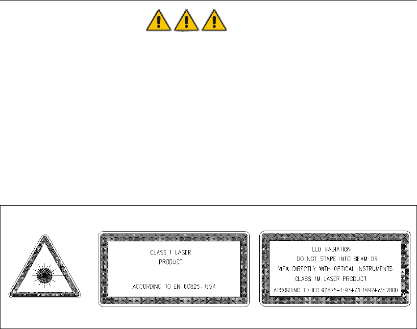
It is sufficient if the signs identifying the laser class and "1" and "1 M" are in the User Manual, as
shown below.
Abb. 2.3.1 Laser Warning Signs in the User Manual in the Pertinent National Language
Classifying the PCB camera Multicolor as laser class "1M" or "1" only applies if no one manipula-
ted with the camera. Make certain that the lacquer on the setting potentiometer on the camera
and on the "PCB camera board modular" is undamaged.
Otherwise there will be a higher risk of an accident due to LED radiation and it is not allowed to
install/continue to operate the PCB camera Multicolor in its current condition.
Cameras with a damaged seal must be returned to Siemens. 2
The voltage for the LED illumination of the PCB camera Multicolor is integrated into the safety
circuit. It is switched off automatically when a protective cover is opened, emergency off is trigge-
red or the component changeover table on the machine frame is unplugged (interface cable).
With "Key-operating switch in service position" the protective function (= shut-off of the LED
camera illumination) is retained. During the assembly the final safety check has to be carried out,
as described in Abschn. 2.11.