00194313-03 - 第62页
2 Assembly Instructions for PCB Camera, Multicolor SIPLACE S-25 HM / S-27 HM 2.5 Preparatory Steps 02/2007 Edition 62 2.5.3 S-25 HM wiring with terminal panel on right -hand side, new version (new rectifier module A2, la…
SIPLACE S-25 HM / S-27 HM 2 Assembly Instructions for PCB Camera, Multicolor
02/2007 Edition 2.5 Preparatory Steps
61
2.5.2 Assembly in the Terminal Panel, LH Side
2.5.2.1 Changing the "Illumination" Cables
The S-25 HM / S-27 HM have 2 "illumination" cables: 2
– Cable "illumination, gantry 1": Item no. 00244260-xx
– Cable "illumination, gantry 2": Item no. 00244261-xx
These cables must be changed first, as described below.
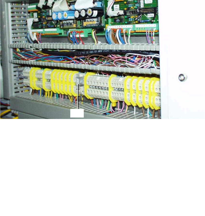
Fig. 2.5.3 Terminal Panel, LH Side, Layout of the Illumination Cables, Gantries 1 and 2
: Open the machine frame doors for terminal panel, LH side.
: Use the circuit diagram Fig. 2.13.6 and Change the two cables "illumination, gantry 1" and "2"
as follows:
: Separate the strands wh, gn, gr, bl which are clamped to terminal X212 - 4 with a connector
sleeve.
: Use the crimping pliers. Now clamp these strands separately as follows, each in a twin con-
nector sleeve from the assembly kit (Section 2.4.1): wh with gn. gr with bl.
: Clamp the 2 changed "Illumination" cables on the terminal panel:
2
2
the strands wh, gn
-> to terminal X212 - 4 (+ 24V),
the strands gn, bl -> to terminal X212 - 9 (+ 50V)
3
4
X212
2 Assembly Instructions for PCB Camera, Multicolor SIPLACE S-25 HM / S-27 HM
2.5 Preparatory Steps 02/2007 Edition
62
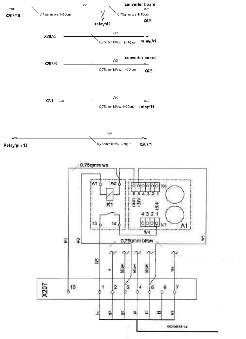
2.5.3 S-25 HM wiring with terminal panel on right-hand side, new version
(new rectifier module A2, lamp-wire connector in cable duct)
2
W1: Ground connection for
relay and converter board
W2: Connection switched
24VDC from X207/3 (only
available if cover is closed)
W3: 24VDC input for converter
board from X207/5
W4: 50VDC output of converter
board to pin 14 of relay
W5: Switched relay output
50VDC to X207/1 (brown wire of
cable 00306880) 2
SIPLACE S-25 HM / S-27 HM 2 Assembly Instructions for PCB Camera, Multicolor
02/2007 Edition 2.5 Preparatory Steps
63
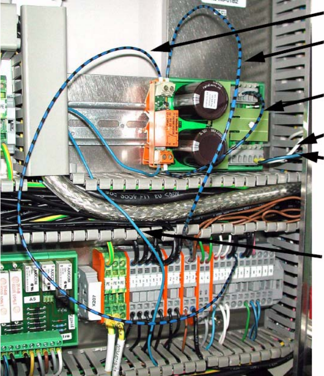
: Open the vertical cable duct on the right.
: Remove the lamp-wire connector with the white, blue-black and blue wires.
2
2
: Wire from X207/5 to relay connection A2.
: Wire from X207/3 to relay connection A1.
If there are no free slots, crimp to existing wire with double ferrule.
: Clamp white wire from the lamp-wire connector to X6/6 (GND).
: Clamp blue-black wire from the lamp-wire connector to X6/5 (+24 V).
: Clamp wire from relay connection 14 to X7/1 (+ 50 V).
: Blue wire from the lamp-wire connector to relay connection 13.
A207/5 to A2
X207/3 to A1
X6/6
X6/5
X7/1
Relay connection 13