00194313-03 - 第64页
2 Assembly Instructions for PCB Camera, Multicolor SIPLACE S-25 HM / S-27 HM 2.5 Preparatory Steps 02/2007 Edition 64 2 2 : T wo in a single ferrule (003442 60-xx and 00344261- xx): Remove green, white, blue and gray wir…
SIPLACE S-25 HM / S-27 HM 2 Assembly Instructions for PCB Camera, Multicolor
02/2007 Edition 2.5 Preparatory Steps
63
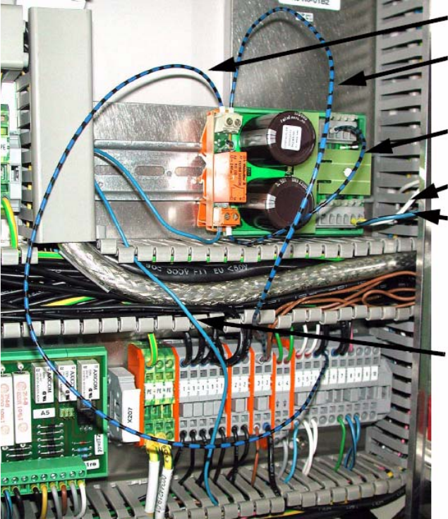
: Open the vertical cable duct on the right.
: Remove the lamp-wire connector with the white, blue-black and blue wires.
2
2
: Wire from X207/5 to relay connection A2.
: Wire from X207/3 to relay connection A1.
If there are no free slots, crimp to existing wire with double ferrule.
: Clamp white wire from the lamp-wire connector to X6/6 (GND).
: Clamp blue-black wire from the lamp-wire connector to X6/5 (+24 V).
: Clamp wire from relay connection 14 to X7/1 (+ 50 V).
: Blue wire from the lamp-wire connector to relay connection 13.
A207/5 to A2
X207/3 to A1
X6/6
X6/5
X7/1
Relay connection 13
2 Assembly Instructions for PCB Camera, Multicolor SIPLACE S-25 HM / S-27 HM
2.5 Preparatory Steps 02/2007 Edition
64
2
2
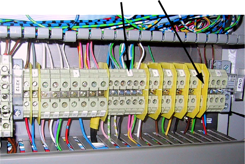
: Two in a single ferrule (00344260-xx and 00344261-xx):
Remove green, white, blue and gray wires from terminal X212/4.
: Remove and insulate brown wire from X212/9 and place in the cable duct.
: Now combine the white and green wires in a single ferrule.
: Then combine the two green and blue wires using a quadruple ferrule.
2
2
X212/4
X212/9
SIPLACE S-25 HM / S-27 HM 2 Assembly Instructions for PCB Camera, Multicolor
02/2007 Edition 2.5 Preparatory Steps
65
2
2
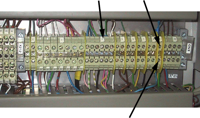
: Clamp the two combined green and white wires to X212/4 (+24V).
: Clamp the combined blue and gray wires to X212/9.
: Remove the blue wire from cable 00306880-xx from the cable duct and clamp to X212/9 using
a ferrule (+50V).
2
2
2
2
2
2
2
2
2
2
X212/9X212/4
X212/9 from cable duct
00306880-xx