00194313-03 - 第84页
2 Assembly Instructions for PCB Camera, Multicolor SIPLACE S-25 HM / S-27 HM 2.12 Illumination Setting 02/2007 Edition 84 2.12.2 Orient ation Aid for Selecting Illumination The following table is derived from empirical v…
SIPLACE S-25 HM / S-27 HM 2 Assembly Instructions for PCB Camera, Multicolor
02/2007 Edition 2.11 Safety Check: Shutdown of Illumination
83
2.11 Safety Check: Shutdown of Illumination
: In succession, activate again - as described above - visible camera illumination at each gantry
and, while the light is starting to flash ON, open a safety hood or a cover (PCB input / PCB
output):
: Check: The light must turn OFF when this occurs. This results from the interruption of the cur-
rent from the voltage regulator module (50 V) by the assemblied safety relay.
: If an error occurs, check and correct the wiring on the basis of the circuit diagrams
in Abschn. 2.13.
: Repeat this procedure with the key-operated switch in the normal position and in the service
position. The vision screen must remain DARK. Continue with the illumination setting.
2.12 Illumination Setting
: Adjust the illumination setting at the station to the current substrate to be placed, proceeding
as described below.
2.12.1 Possible Illumination Settings and Selection Criteria
The following types of illumination are possible with the PCB camera Multicolor by using the per-
tinent setting (see Abschn. 2.12.3): 2
– Standard light:
Using this mixture of white and IR light it is possible to recognize a broad range of fiducials. By
selecting special types of illumination, the contrast of the image can be improved and, as a
consequence, the range of recognizable fiducials increased.
– White light:
This is used for standard PCBs (tinned fiducials).
– Blue oblique illumination:
By using this light, an obvious improvement in contrast can usually be attained where bright
fiducials on a light base material are involved, e.g., on ceramic or CEM. In a few instances,
fiducials covered by solder resist can also be recognized better on a light background.
– IR light:
It is usually practical to use this type of illumination for fiducials that are covered by solder resist
or for fiducials on flex material. It may also be possible to improve recognition where silver-pla-
tinum fiducials on ceramic are involved. Ascertain this in advance by conducting a trial cen-
tering and/or a trial placement.

2 Assembly Instructions for PCB Camera, Multicolor SIPLACE S-25 HM / S-27 HM
2.12 Illumination Setting 02/2007 Edition
84
2.12.2 Orientation Aid for Selecting Illumination
The following table is derived from empirical values and is therefore only to serve as an orientation
aid. A few materials often exhibit very drastic fluctuations (particularly in the case of CEM1), the-
refore the best illumination has to be ascertained through testing. In each instance this is done by
selecting the setting for illumination during the course of a sample placement with recognition of
the position of the pertinent PCBs or ceramic substrates. 2
Base material Fiducial material Oblique illu-
mination
BLUE
Infrared
light
White light
FR 4 Tin x
Ceramic NiAu, Cu, AgPl x
Ceramic AgPt x
CEM1 Bright copper fiducials,
tin
x
CEM1 Fiducials covered by sol-
der resist
(x) x
Flex on alumi-
num carrier
x
SIPLACE S-25 HM / S-27 HM 2 Assembly Instructions for PCB Camera, Multicolor
02/2007 Edition 2.12 Illumination Setting
85
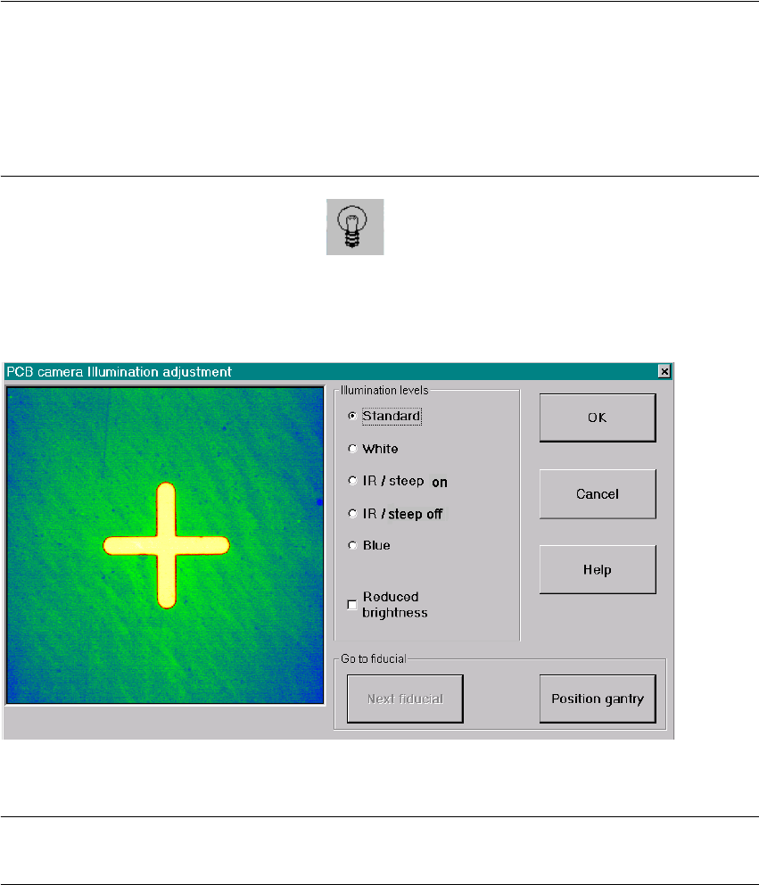
2.12.3 Setting the Illumination
The best illumination selection must be ascertained by using the function "Test fiducials" or the
substrate to be populated. 2
NOTE:
The processes which must be executed prior to setting the illumination are described in detail in
the section "Teaching Fiducials" or "Teaching Synthetic Fiducials" of the User Manual, Software
version SR 502.xx.
During them, the current substrate or PCB is moved onto the processing belt of the conveyor and
mechanically centered / clamped in place. 2
: Select the ICON "Setting illumination"
: In the "illumination" menu select the "Setting illumination" button.
The following screen will appear:
Fig. 2.12.1 Screen: "Setting the Illumination"
NOTE:
Utilize Abschn. 2.12.2 and the table in Abschn. 2.12.3 to select the best type of illumination. 2
: Select the desired illumination level by activating the pertinent radio button.
: Select the complete or the reduced brightness by activating or deactivating the rectangular
field.