00194313-03 - 第92页
2 Assembly Instructions for PCB Camera, Multicolor SIPLACE S-25 HM / S-27 HM 2.13 Attachments: PCBs, Cables and Circuit Diagrams 02/2007 Edition 92 2.13.2 Circuit Diagrams for Assembly on S-25 HM 2 Fig. 2.13.6 S-25 HM: A…
SIPLACE S-25 HM / S-27 HM 2 Assembly Instructions for PCB Camera, Multicolor
02/2007 Edition 2.13 Attachments: PCBs, Cables and Circuit Diagrams
91
2
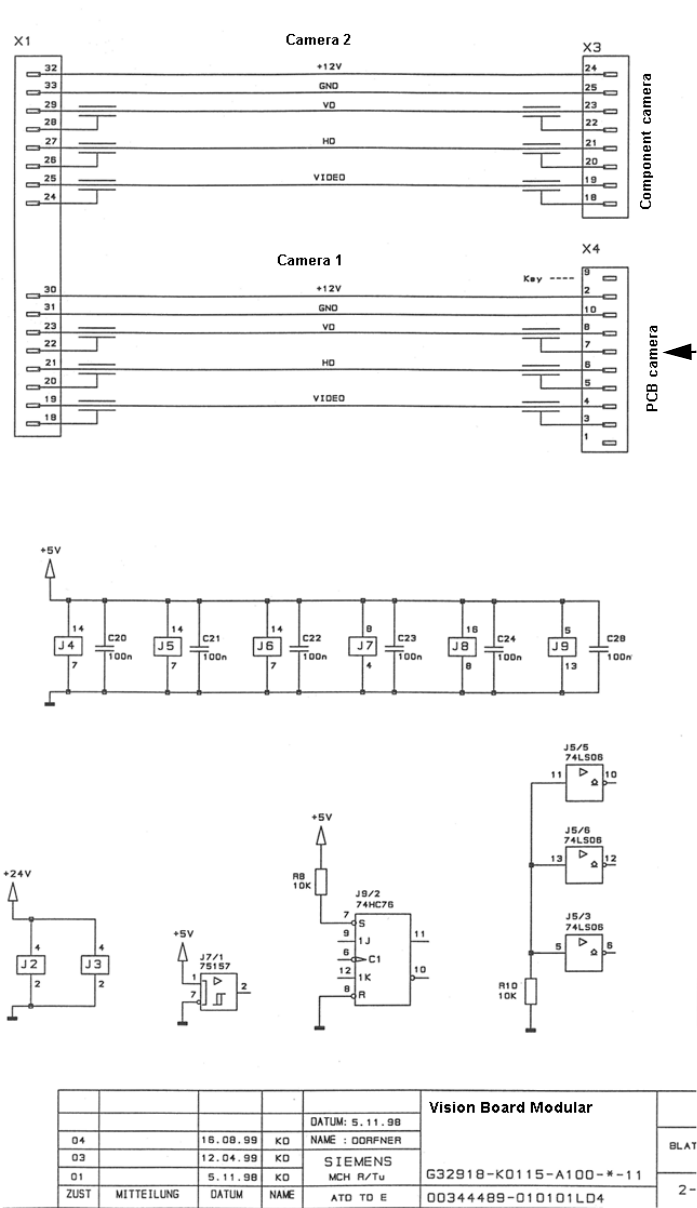
Fig. 2.13.5 Circuit Diagr. Vision Board, Modular: Connect. PCB Camera (Normal Illuminat.) or Multicolor
PCB camera (normal illumination)
or of the PCB camera Multicolor
Cable "Illumination" of the subgantry
2 Assembly Instructions for PCB Camera, Multicolor SIPLACE S-25 HM / S-27 HM
2.13 Attachments: PCBs, Cables and Circuit Diagrams 02/2007 Edition
92
2.13.2 Circuit Diagrams for Assembly on S-25 HM
2
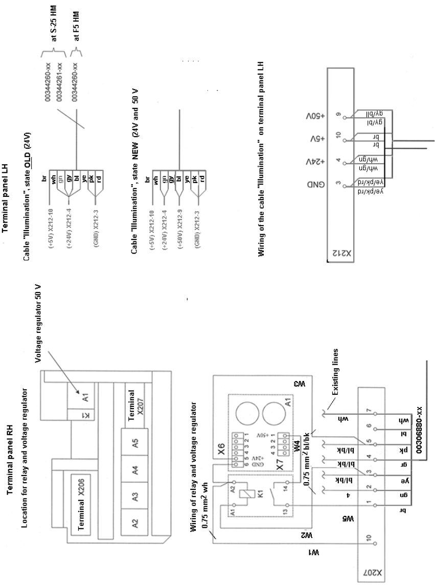
Fig. 2.13.6 S-25 HM: Assembly the Voltage Module, 50 V, Circuit Diagram 00357863-010101LD3
SIPLACE S-25 HM / S-27 HM 2 Assembly Instructions for PCB Camera, Multicolor
02/2007 Edition 2.13 Attachments: PCBs, Cables and Circuit Diagrams
93
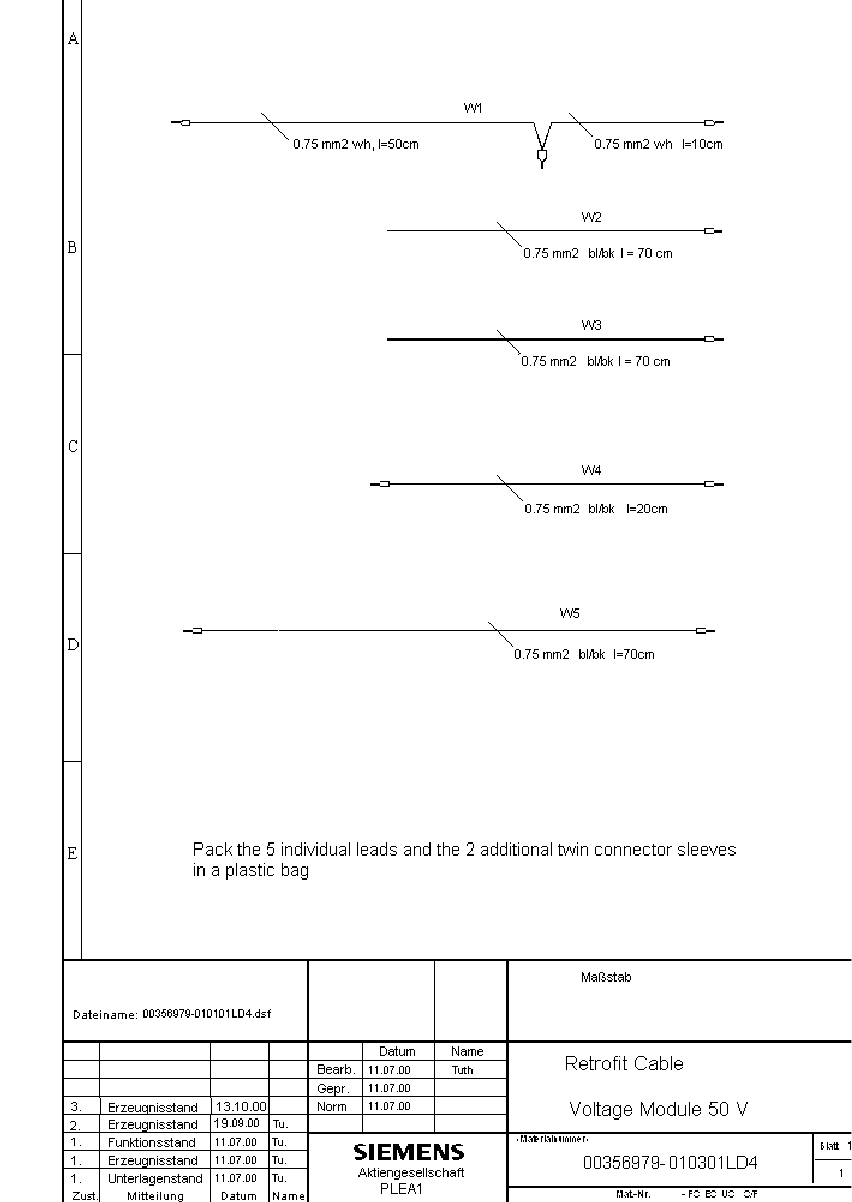
Fig. 2.13.7 S-25 HM: Assembly Kit Cable for 24 V/50 V Module