Infinity DI.pdf - 第17页
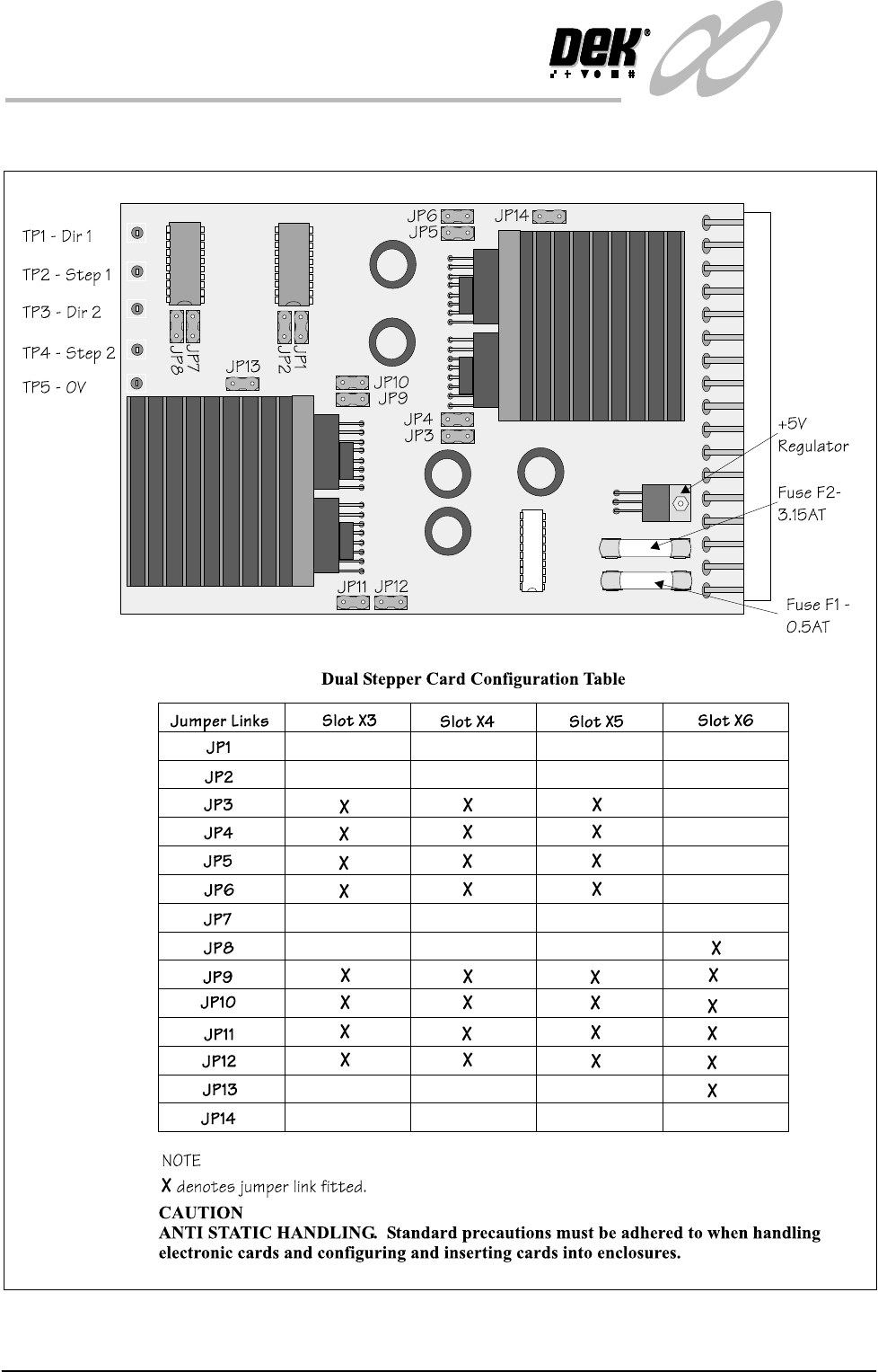
1.12 Infinity Dual Imag e Manual Chapter Issue 4 Aug 01 INFINITY TECHNIC AL RE FERENCE DRIVE S AND SEN SORS Steppe r Drive Card The link settings for the Dual Image stepper driv e card are shown belo w: Figure 1-8 Dual S…

INFINITY
TECHNICAL REFERENCE
DRIVES AND SENSORS
Chapter Issue 4 Aug 01 Infinity Dual Image Manual 1.11
DRIVES AND SENSORS
Drives
Sensors
Name Type Control Card Functional Description
Screen Load Stepper 13M1 Stepper Stepper Drive
X6 Channel 2
Moves the screen load actuators (2 on
each screen rail) via a drive shaft and
two pulley system
Name
Type
Control Card Functional Description
Bar Code Reader
(Optional)
Laser Scanner and
(Trigger) diffuse
opto sensor
X7
4 Channel RS232
Trigger sensor detects product and
switches the reader on. Laser scanner
reads the bar code label to identify the
product being printed.
Product Sensor Diffuse Opto MultiMove (IN8) Alternative to the bar code reader
option. Determines which product is
on the input conveyor.
Board Present Diffuse Opto MultiMove (IN9) Confirms the presence of a board on
the input conveyor.
Screen at Front Long throw opto
through beam
MultiMove X11
(IN6)
Senses when the screen is clear of the
front of the chase. Used by the soft-
ware to determine whether a stencil
load or unload is viable.
Screen at Rear Long throw opto
through beam
MultiMove X11
(IN5)
Senses when the screen is clear of the
rear of the chase. Used by the soft-
ware to determine whether a stencil
load or unload is viable.
Screen at Centre Long throw opto
through beam
MultiMove X11
(IN4)
Senses when the screen is clear of the
centre of the chase. Used by the soft-
ware to determine whether a stencil
load or unload is viable.
Screen in Transit Front Diffuse opto with
background sup-
pression
MultiMove X11
(IN7)
Senses the stencil position during a
stencil unload. Prevents the stencil
from hitting the machine cover.
Screen in Transit Rear Diffuse Opto MultiMove X11
(IN1)
Senses the stencil position during a
stencil unload. Prevents the stencil
from hitting the machine cover
L/H Coupling Rear
Extended
Reed Switch MultiMove X11
(IN3)
Detects when the left hand screen
coupling is fully extended.
R/H Coupling Rear
Extended
Reed Switch MultiMove X11
(IN3)
Detects when the right hand screen
coupling is fully extended.
1.12 Infinity Dual Image Manual Chapter Issue 4 Aug 01
INFINITY
TECHNICAL REFERENCE
DRIVES AND SENSORS
Stepper Drive Card The link settings for the Dual Image stepper drive card are shown below:
Figure 1-8 Dual StepperDrive PCB
INFINITY
TECHNICAL REFERENCE
DRIVES AND SENSORS
Chapter Issue 4 Aug 01 Infinity Dual Image Manual 1.13
Four Channel
Comms Card
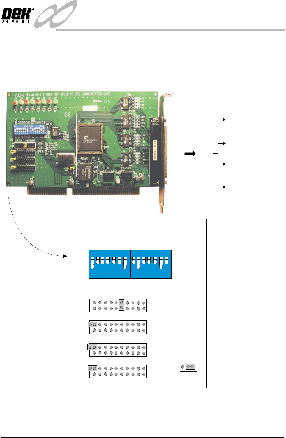
The communications card is fitted to slot X7 of the machine pc. It is used to
interface with external communications devices such as the remote bar code
reader, infra-red link and the stencil bar code reader. This card uses a shared
interrupt (IRQ) level for the available options. The correct DIP switch and
jumper link settings are shown below.
Figure 1-9 4 Channel RS232 Comms Card Set Up
3SK27 3PL27
P1 - 3PL19 - Stencil
Barcode Reader - COM5
P2 - 3PL20 - Remote
Barcode Reader -COM6
P3 - 3PL20 -
Spare -COM7
P4 - 3PL21 -
Spare -COM8
12
3
4
56
7
ON
SPEED
A3
A4
A5
A6
A7
A8
S2
12
3
4
56
7
ON
MODE0
MODE1
A4
A5
A6
A7
A8
S1
3 4 5 6 7 9 10 11 12 15
JP1
CH#1
3 4 5 6 7 9 10 11 12 15
JP2
CH#2
3 4 5 6 7 9 10 11 12 15
JP3
CH#3
3 4 5 6 7 9 10 11 12 15
JP4
CH#4
IRQ
BASE ADDRESS
VECTOR ADDRESS
JP15
123
MODE0: ON-Share IRQ
OFF-Indep.IRQ
MODE1: ON-Standard
OFF-Enhance
SPEED: ON-8x
OFF-1x