Infinity DI.pdf - 第26页
INFINITY TECHNI CAL REFEREN CE SEQUEN CES Chapter Issu e 4 Aug 01 Infinity Dual Imag e Manual 1.21 8. The screen clamps the screen. Normal board to screen alignment takes place. Figur e 1-15 Load Sequence Rear Image -Pr …
1.20 Infinity Dual Image Manual Chapter Issue 4 Aug 01
INFINITY
TECHNICAL REFERENCE
SEQUENCES
Screen Shuttle Sequence - Image at the Rear
Automatic Load - Rear Screen Shuttle
This operation may be the first or a follow-on operation after a front load print
sequence. Hence, a batch of front loaded boards may be printed first and this
batch printed second or vice versa.
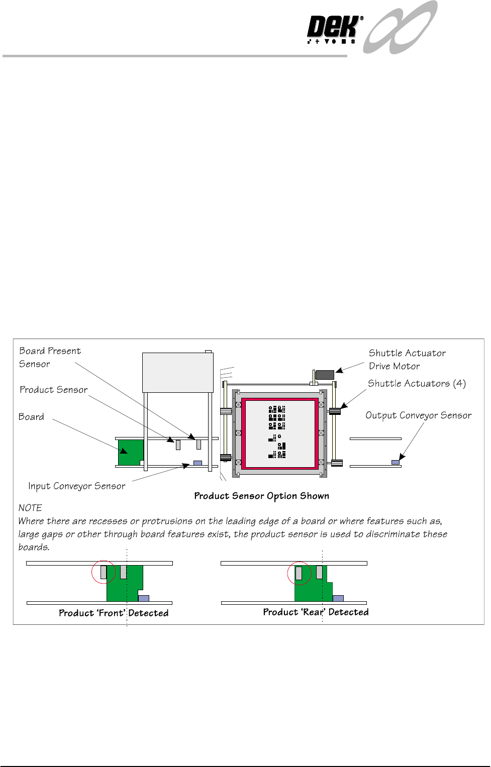
1. The first board in the batch is fed to the inroad conveyor sensor where it
stops.
2. The machine interrogated either the bar code reader (BCR) or the board
present sensor to check that the board has arrived ready for loading (for the
BCR, the correct product file is loaded).
3. If the presence of a board is detected by the product sensor (option) then the
board is deemed of the type for the product file - and set in accordance with
this configuration, the product file is loaded.(See Note below)
4. As the board details have been confirmed, the machine starts the shuttle
action of the screen.
Figure 1-14 Load Sequence Rear Image _ Product Load
5. The chase clamps release the screen.
6. The front screen shuttle actuators grip the screen at the side, the rear actuators
remain engaged in the slots at the rear of the screen.
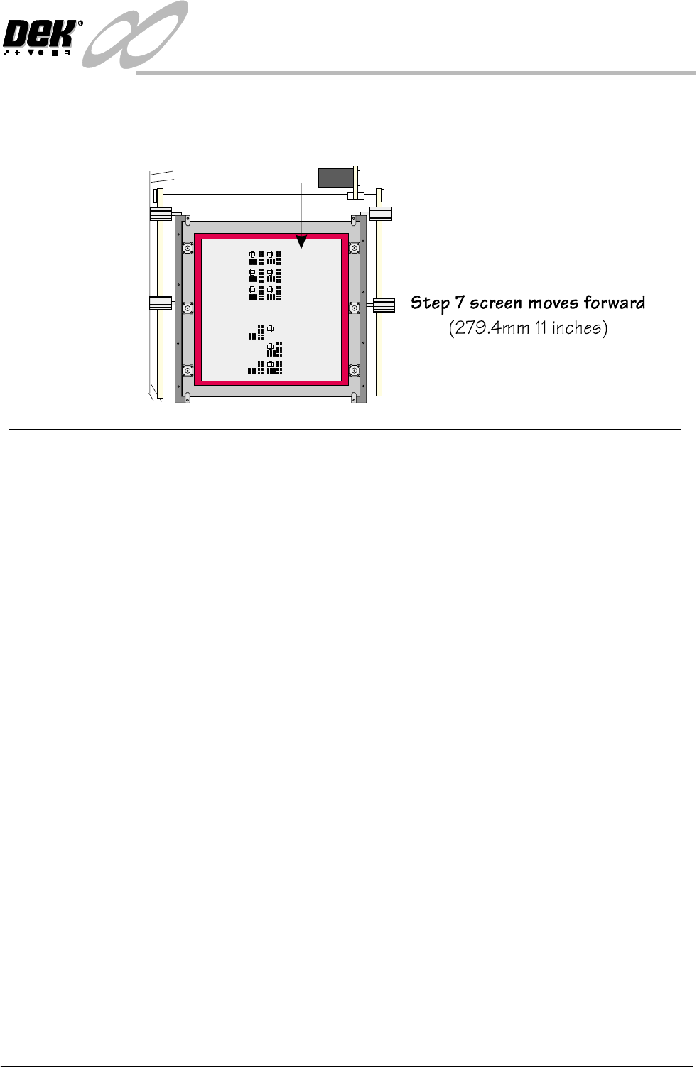
7. The screen shuttle actuators move the screen rearward in the chase by the
amount given in the product file.
INFINITY
TECHNICAL REFERENCE
SEQUENCES
Chapter Issue 4 Aug 01 Infinity Dual Image Manual 1.21
8. The screen clamps the screen. Normal board to screen alignment takes place.
Figure 1-15 Load Sequence Rear Image -Product Load (Continued)

1.22 Infinity Dual Image Manual Chapter Issue 4 Aug 01
INFINITY
TECHNICAL REFERENCE
POSITIONING
POSITIONING All sensors are positioned on the input frame and take into account any features
that may prevent product from being correctly loaded. As the parameters for
the products differ, board lengths and widths may vary, with the exception of the
screen home position, fixed positions are not quoted. All other positions for the
system are shown in the various chapters of the Infinity Technical Reference
Manual.
Screen Home
Position
Refer to the Infinity Technical Reference Manual for details on setting this
parameter.
Distance to Image
Reference Position
This parameter is used to set the position of the product images.
1. Tape the product image to the correct stencil such that the images line up, see
figure overleaf.
2. Measure the distance to the front edge of the product with respect to the
leading edge on the rear of the stencil or skis.
3. Input the value into each product file. See section: Adjustments and Settings
- Distance to Image.
4. Remove the products from the rear of the stencil, fit the stencil into the
machine and test (the images should align when the rising table lifts the
product to the print position). Adjust the parameter in the product file if
necessary.