Infinity DI.pdf - 第29页
1.24 Infinity Dual Imag e Manual Chapter Issue 4 Aug 01 INFINITY TECHNIC AL RE FERENCE ADJUS TMENT S AND SET TINGS ADJUSTMEN TS AND SETTINGS Board Present Sensor The board present sensor is used to indi cate to indicate …
INFINITY
TECHNICAL REFERENCE
POSITIONING
Chapter Issue 4 Aug 01 Infinity Dual Image Manual 1.23
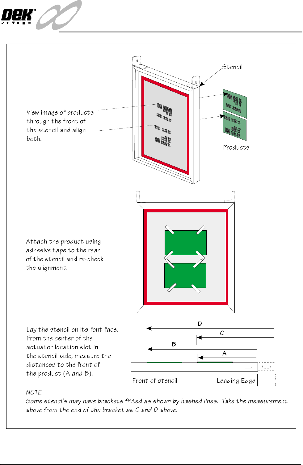
Figure 1-16 Distance to Image Position Setting
1.24 Infinity Dual Image Manual Chapter Issue 4 Aug 01
INFINITY
TECHNICAL REFERENCE
ADJUSTMENTS AND SETTINGS
ADJUSTMENTS AND SETTINGS
Board Present Sensor
The board present sensor is used to indicate to indicate to the Infinity machine
that a board is present on the input conveyor. At the start of a run a board is fed
along the input conveyor until it reaches the conveyor sensor. At this point a
board should be detected by the board present sensor regardless of the board size,
shape or features. The board present sensor must therefore be located in such a
position that it always registers the board being present when it has arrived at the
halt position on the input conveyor.
The position can be moved for the alignment by pushing the sensor against the
spring on the rail and then sliding it to the correct location. Similarly, the position
of the sensor in the ’Y’ direction can be set by adjusting the position of the rail
it is mounted on. The clamp handles are lifted against the spring to allow them
to move.
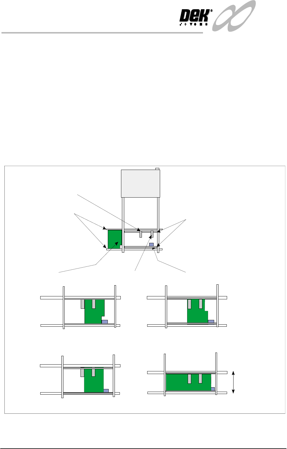
Figure 1-17 Board Present Sensor Adjustment
Board
Input Conveyor Sensor
Input Conveyor
Sensor Mounting Rails
Board Present Sensor On, Product Sensor Off
Board Present Sensor On, Product Sensor Off
Board Present Sensor On, Product Sensor On
Width adjusted
Same Product
Different Products
Examples:
Board Present Sensor On, Product Sensor On.
Board Present Sensor
Product Sensor
INFINITY
TECHNICAL REFERENCE
ADJUSTMENTS AND SETTINGS
Chapter Issue 4 Aug 01 Infinity Dual Image Manual 1.25
Product Sensor The product sensor option enables product size or a feature to be used as a means
of detecting which program is to be used by the print process.
To set up the sensors, a board is loaded onto the input conveyor. The board stops
at the conveyor sensor. The product sensor should be placed such that at the point
where the board stops on the conveyor, the sensor is ON for one type and OFF
for other products. On is indicated by the green LED switching on. Where the
board has a recess or protrusion, the different leading edge perimeter (as shown
in the diagram below) is used to distinguish between board sizes and hence
which process program is to be used.
To adjust this position, load along board (or board with a feature such as a recess
or protrusion), the sensor is spring loaded. Push the sensor against the rail and
slide it along until the sensor switches from on to off and then move it back to
the on position. Load a short board (or flip the board over and load it) so that the
short board or recess area now clears the sensor to switch it off.
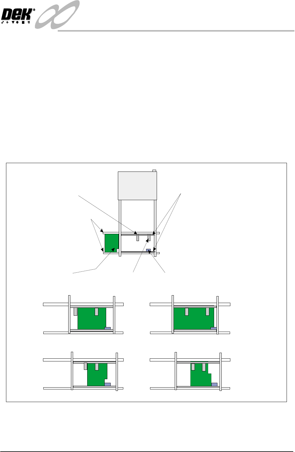
Figure 1-18 Adjustment of the Product Sensor
Board
Input Conveyor Sensor
Sensor Mounting Rails
Input Conveyor
Product Sensor - Sensor Off
Product Sensor - Sensor On
Examples:
Different Products
Same Product - Product Feature Detected
Short Board In - Product Sensor Off
Long Board In - Product Sensor On
Board Present
Sensor
Product Sensor