Infinity DI.pdf - 第30页
INFINITY TECHNI CAL REFEREN CE ADJUS TMEN TS AND SETTI NGS Chapter Issu e 4 Aug 01 Infinity Dual Imag e Manual 1.25 Pr oduct Sensor The product sensor option enables product size or a feat ure to be used as a means of de…
1.24 Infinity Dual Image Manual Chapter Issue 4 Aug 01
INFINITY
TECHNICAL REFERENCE
ADJUSTMENTS AND SETTINGS
ADJUSTMENTS AND SETTINGS
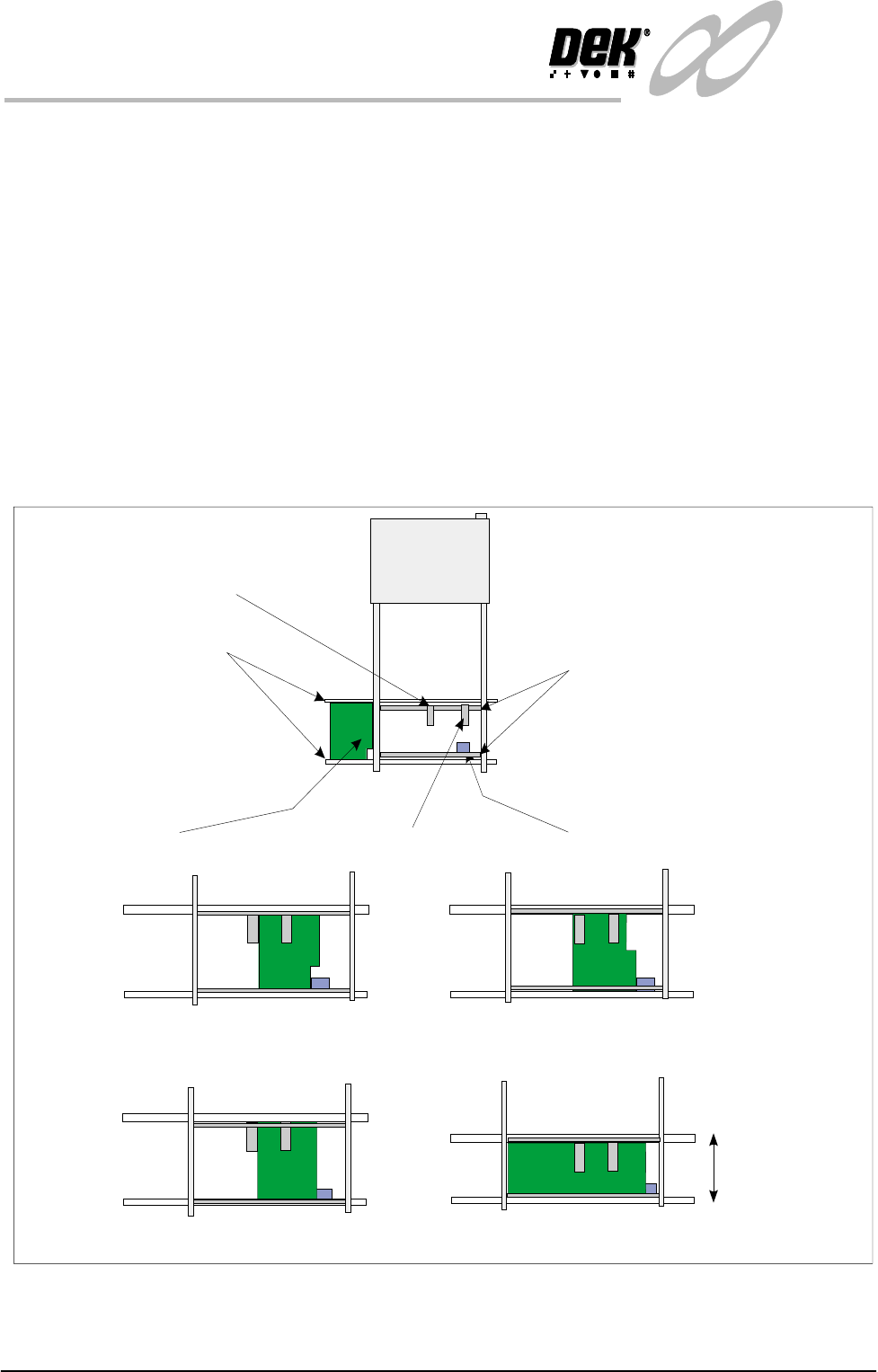
Board Present Sensor
The board present sensor is used to indicate to indicate to the Infinity machine
that a board is present on the input conveyor. At the start of a run a board is fed
along the input conveyor until it reaches the conveyor sensor. At this point a
board should be detected by the board present sensor regardless of the board size,
shape or features. The board present sensor must therefore be located in such a
position that it always registers the board being present when it has arrived at the
halt position on the input conveyor.
The position can be moved for the alignment by pushing the sensor against the
spring on the rail and then sliding it to the correct location. Similarly, the position
of the sensor in the ’Y’ direction can be set by adjusting the position of the rail
it is mounted on. The clamp handles are lifted against the spring to allow them
to move.
Figure 1-17 Board Present Sensor Adjustment
Board
Input Conveyor Sensor
Input Conveyor
Sensor Mounting Rails
Board Present Sensor On, Product Sensor Off
Board Present Sensor On, Product Sensor Off
Board Present Sensor On, Product Sensor On
Width adjusted
Same Product
Different Products
Examples:
Board Present Sensor On, Product Sensor On.
Board Present Sensor
Product Sensor
INFINITY
TECHNICAL REFERENCE
ADJUSTMENTS AND SETTINGS
Chapter Issue 4 Aug 01 Infinity Dual Image Manual 1.25
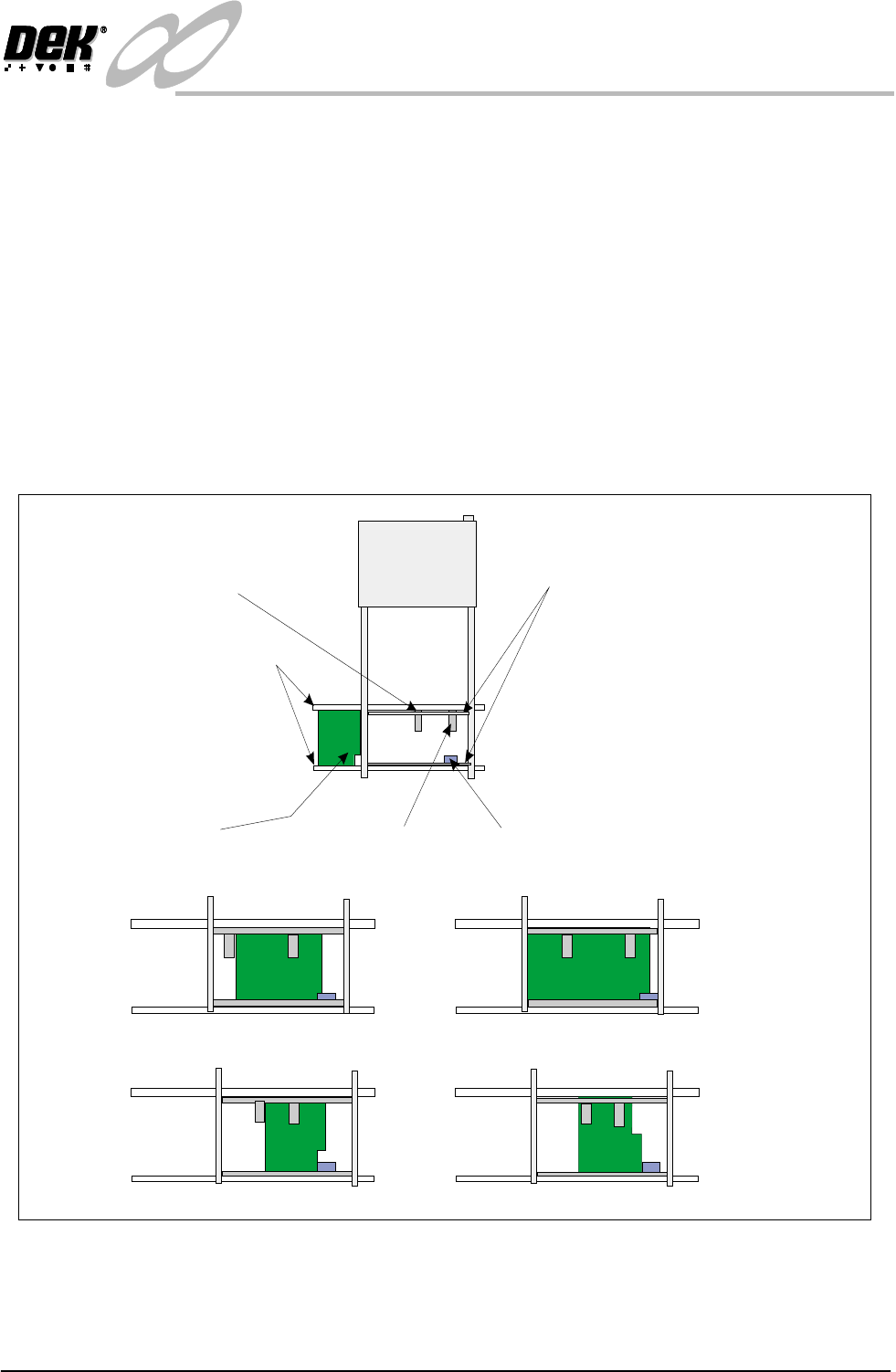
Product Sensor The product sensor option enables product size or a feature to be used as a means
of detecting which program is to be used by the print process.
To set up the sensors, a board is loaded onto the input conveyor. The board stops
at the conveyor sensor. The product sensor should be placed such that at the point
where the board stops on the conveyor, the sensor is ON for one type and OFF
for other products. On is indicated by the green LED switching on. Where the
board has a recess or protrusion, the different leading edge perimeter (as shown
in the diagram below) is used to distinguish between board sizes and hence
which process program is to be used.
To adjust this position, load along board (or board with a feature such as a recess
or protrusion), the sensor is spring loaded. Push the sensor against the rail and
slide it along until the sensor switches from on to off and then move it back to
the on position. Load a short board (or flip the board over and load it) so that the
short board or recess area now clears the sensor to switch it off.
Figure 1-18 Adjustment of the Product Sensor
Board
Input Conveyor Sensor
Sensor Mounting Rails
Input Conveyor
Product Sensor - Sensor Off
Product Sensor - Sensor On
Examples:
Different Products
Same Product - Product Feature Detected
Short Board In - Product Sensor Off
Long Board In - Product Sensor On
Board Present
Sensor
Product Sensor
1.26 Infinity Dual Image Manual Chapter Issue 4 Aug 01
INFINITY
TECHNICAL REFERENCE
ADJUSTMENTS AND SETTINGS
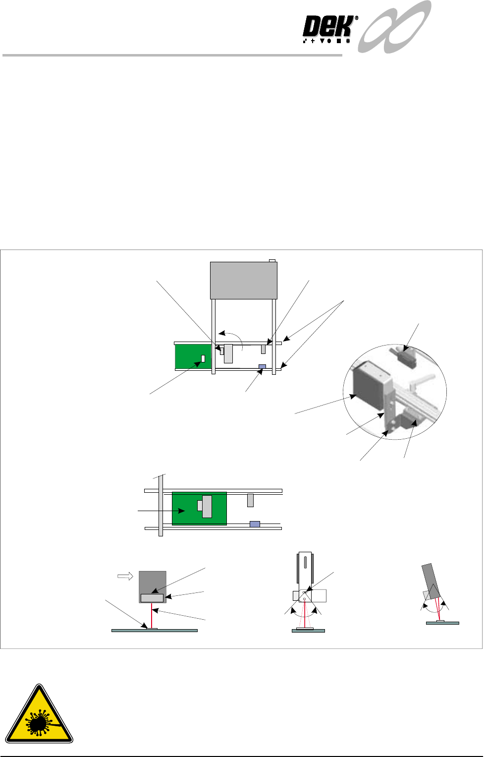
Bar Code Reader The Bar Code Reader (BCR) option reads the code of a product to be printed.
This allows the machine to be automatically set up in software to the product
being used. a sensor mounted before the reader triggers the readrer on. The BCR
must be adjusted to the correct angle for reading the label. Bright or shinylabels
act as a mirror flooding the sensor and giving incorrect readings. Conversely,
dark or dull labels make it hard for the reader to differentiate the bars on the label
giving incorrect readings.
To set up the BCR, a board is loaded onto the input conveyor. The board passes
beneath the trigger sensor that switches the reader momentarily on. The label is
read and confirmation of the correct product occurs. The board continues to the
conveyor sensor where it stops and is detected by the board present sensor. This
is the correct operation of the reader and no adjustment is necessary. If the sensor
mis-reads then the angle, height and orientation of the reader may be adjusted.
Figure 1-19 Adjusting the Bar Code Reader
WARNING
LASER LIGHT SOURCE. THE BAR CODE READER UTILIZES A
LASER TO SCAN THE BAR CODE, DO NOT LOOK DIRECTLY IN
TO THE READER OR AT THE LIGHT DIRECTLY REFLECTED
FROM A SURFACE, AS SERIOUS DAMAGE CAN OCCUR TO THE
Board and Bar Code Label
Input Conveyor Sensor
Trigger Sensor
Tilt Adjust Screw
(15 of tilt)
0
Bar Code Reader
Scan
Bar Code Label
Input Conveyor
Board Present
Sensor
Board Present
Sensor
Bar Code Reader and Trigger Sensor
(can be turned through 90 )
0
The Bar Code label is read
before the board reaches
the Conveyor Sensor.
Movement
View on Arrow A
Side View
A
BCR
Height Adjustment
Bracket
Rotate Adjustment
Tilt Adjustment