Infinity DI.pdf - 第38页
INFINITY TECHNI CAL REFEREN CE ADJUS TMEN TS AND SETTI NGS Chapter Issu e 4 Aug 01 Infinity Dual Imag e Manual 1.33 Figure 1-29 Select Product Sensor NO T E Sensor Off and Sensor On ar e names given to the pr oduct senso…
1.32 Infinity Dual Image Manual Chapter Issue 4 Aug 01
INFINITY
TECHNICAL REFERENCE
ADJUSTMENTS AND SETTINGS
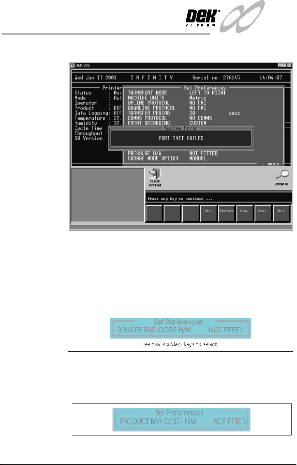
Bar Code Read
Errors
If there is a poor connection or a break in the lead from the reader the error
message panel below is displayed:
Figure 1-26 Bar Code Read Failure
Sensors Set Up To set the product sensors option the following pages are edited.
Set Preferences In Set Preferences, disable the remote bar code and the product bar code
functions.
To edit the product sensor follow the procedure below:
1. Select Maint. (F8 Function Key).
2. Select Set Prefs (F5).
Figure 1-27 Set Preferences - Deselect the Remote Bar Code Reader
3. Select Exit when complete.
4. Select Maint. (F8).
5. Select Set Prefs. (F5).
Figure 1-28 Set Preferences -Deselect the Product Bar Code Reader
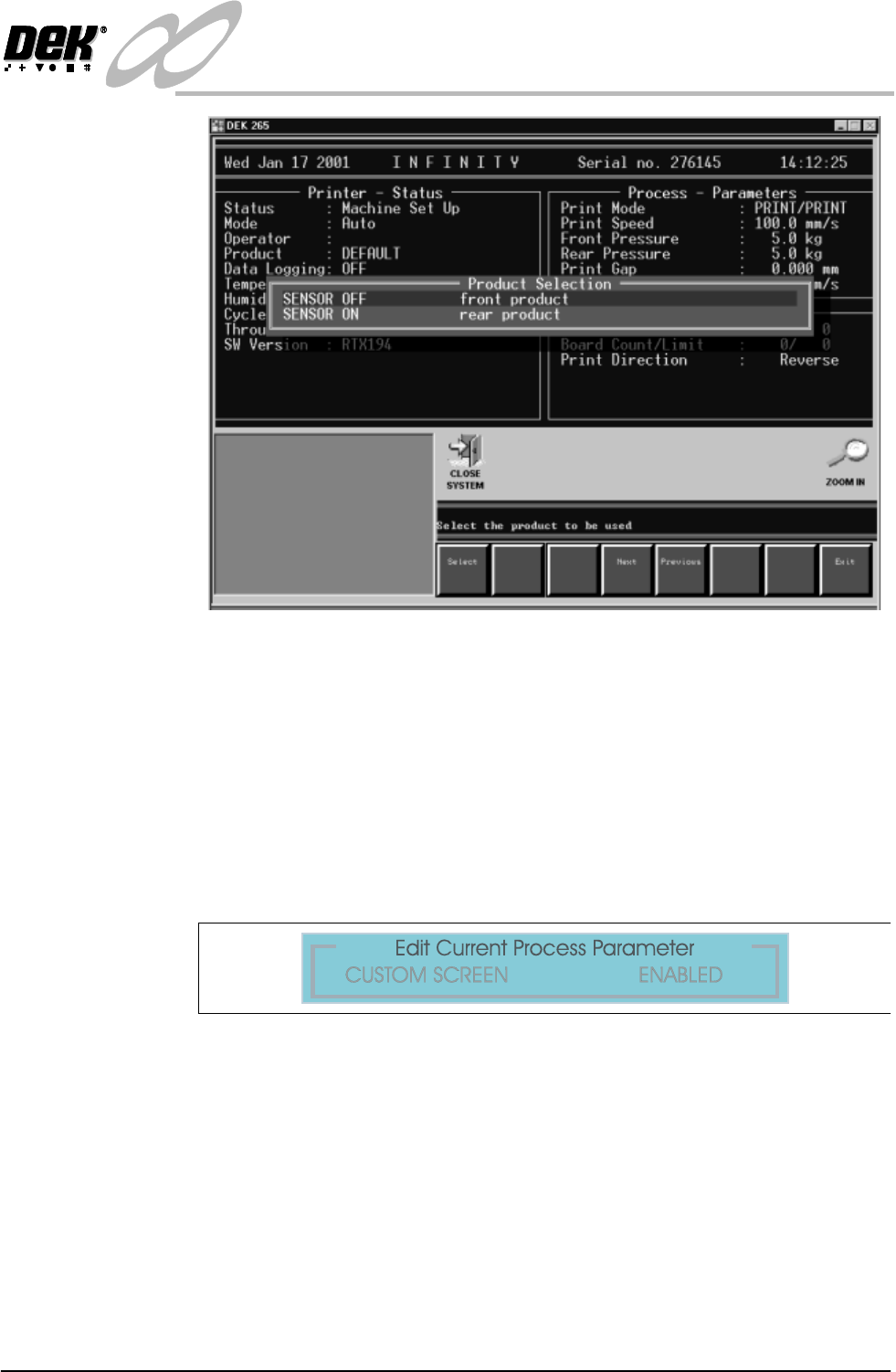
6. Select the Product e.g., the front product.
INFINITY
TECHNICAL REFERENCE
ADJUSTMENTS AND SETTINGS
Chapter Issue 4 Aug 01 Infinity Dual Image Manual 1.33
Figure 1-29 Select Product Sensor
NOTE
Sensor Off and Sensor On are names given to the product sensor, this
distinguishes it when selecting for example:- The Front Product.
After selection the Load Data page (if in load data mode) or Edit Data (if in
edit data mode) is displayed. The product can be loaded or parameters edited
in the standard way.
7. Before dual image can be operated, in Edit Process Parameters scroll down
the page until Custom Screen is displayed. Select Enabled.
Figure 1-30 Set Custom Screen to Enabled
1.34 Infinity Dual Image Manual Chapter Issue 4 Aug 01
INFINITY
TECHNICAL REFERENCE
ADJUSTMENTS AND SETTINGS
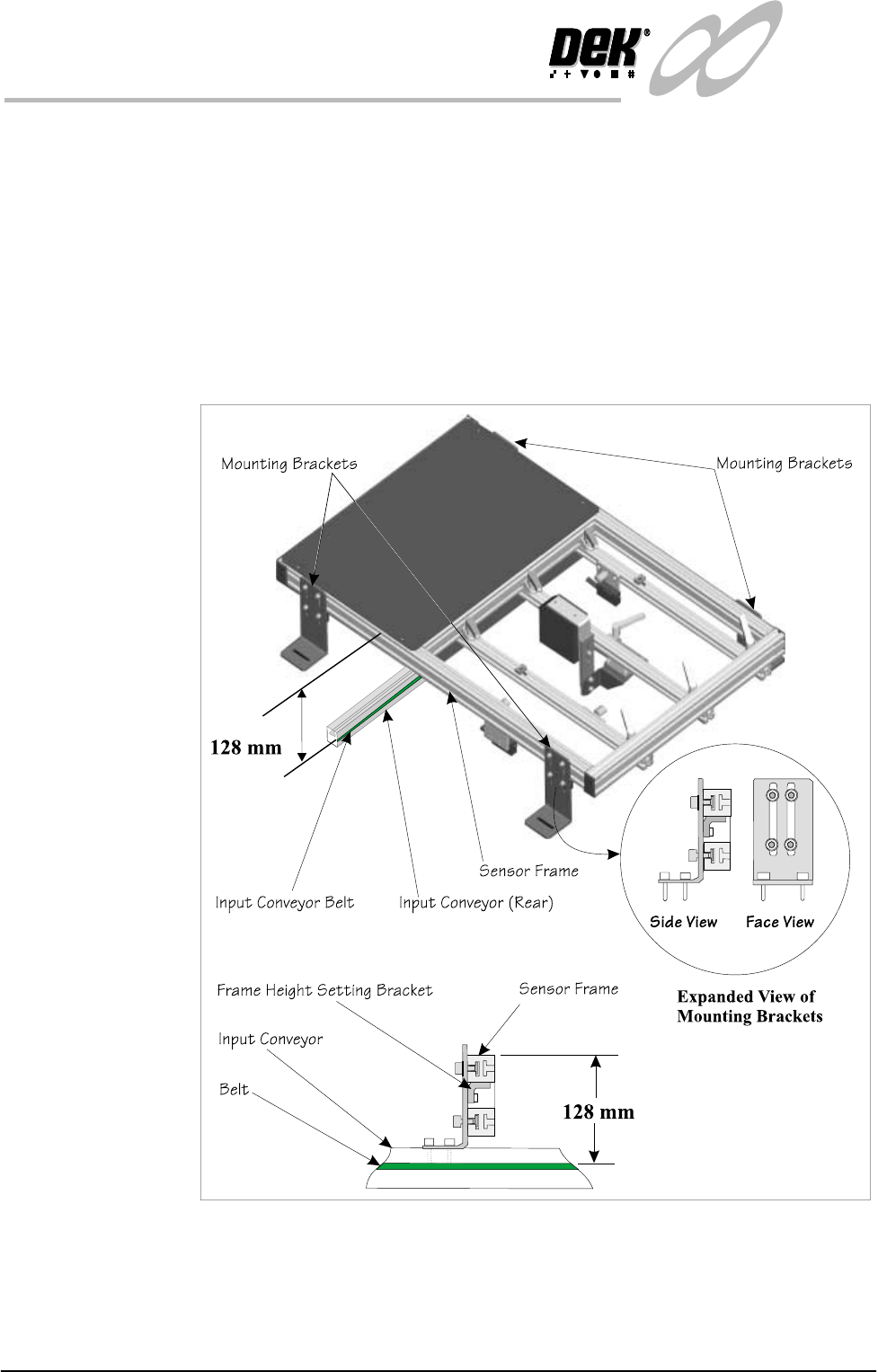
Sensor Frame The sensor frame can be height adjusted, this optimizes the reading capability
of the sensors. Setting the height as shown is good for all sensor types.
Frame Height
Setting
The mounting brackets are secured in the ‘T’ slots of the sensor frame and onto
the conveyor rails. The height of the frame should be set to the dimension shown
(128mm from the top of the conveyor belt to the top of the frame section). The
smaller bracket at the rear of the mounting bracket (Frame Height Setting
Bracket) maintains this height adjustment, it is set by sliding it in its slot up to
the underside of the sensor frame where it is locked. Once set, the brackets may
be moved to a new location (e.g., where rail width needs adjusting) without the
need to reset the height. Once the height has been set, the correct focus for the
sensors is maintained
Figure 1-31 Sensor Frame Height Adjustment