Infinity DI.pdf - 第42页
INFINITY TECHNI CAL REFEREN CE CALIBRATION Chapter Issu e 4 Aug 01 Infinity Dual Imag e Manual 1.37 CALIBRATION For calibration of indi vidual modules, reference should be made to the rele vant chapter of the Infinity T …
1.36 Infinity Dual Image Manual Chapter Issue 4 Aug 01
INFINITY
TECHNICAL REFERENCE
ADJUSTMENTS AND SETTINGS
Fitting the Frame
to the Conveyor
If the frame has been moved from its original position to the opposite input
conveyor, it needs to be fitted to the input conveyor framework.
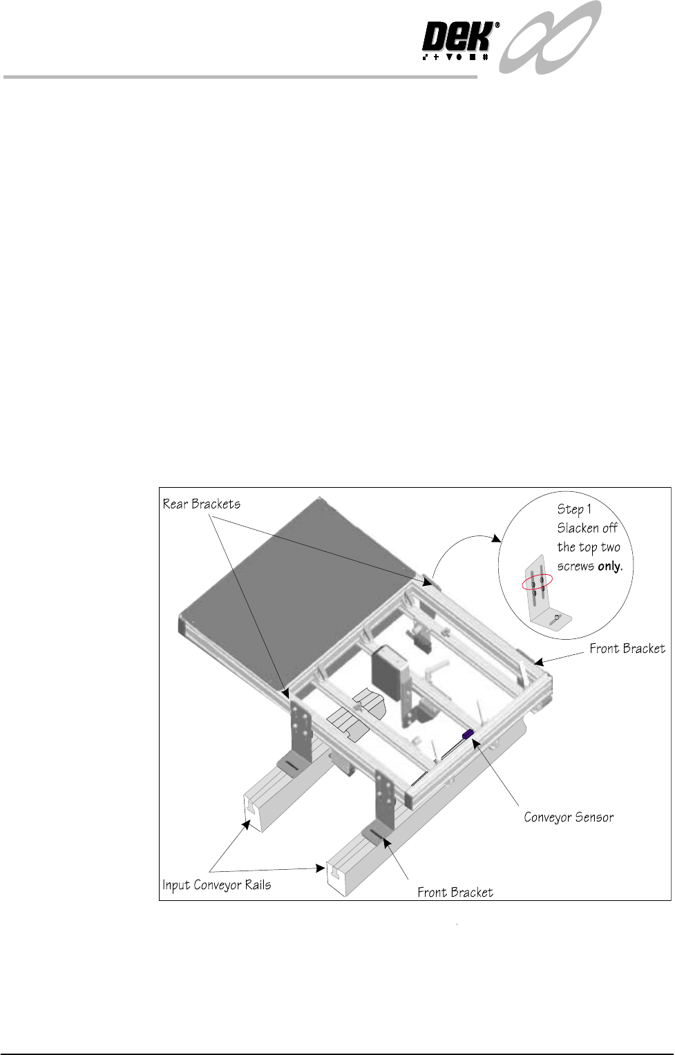
1. Slacken the top two screws holding the rear brackets.
2. Place the frame on the conveyor with the front brackets resting on the front
conveyor rail.
3. Roughly position the rear corner brackets so that they rest on the rear
conveyor rail. Make sure that the corner brackets do not interfere with board
transport.
4. Position the frame left to right such that the ‘Board Present Sensor’ is
roughly aligned with the conveyor sensor.
5. Fit the screws and nuts to loosely hold the four corner brackets to the
conveyor ‘T’ slots
6. Check the frame to conveyor height setting - 128 mm from the top of the
frame to the top of the conveyor belt. If necessary slacken off the lower two
screws on each of the corner brackets (Step 1 shows the top two screws only,
slackened off) and adjust as necessary
7. Fit the cables from the rear service panel to the frame. Bar code reader
connects to 6SK17 the ‘Board Present Sensor’ connects to 6SK21 while the
‘Product Sensor’ connects to 6SK20. Tie wrap the cables to secure.
Figure 1-33 Fitting the Frame to the Machine

INFINITY
TECHNICAL REFERENCE
CALIBRATION
Chapter Issue 4 Aug 01 Infinity Dual Image Manual 1.37
CALIBRATION For calibration of individual modules, reference should be made to the relevant
chapter of the Infinity Technical Reference Manual.
1.38 Infinity Dual Image Manual Chapter Issue 4 Aug 01
INFINITY
TECHNICAL REFERENCE
DIAGNOSTICS
DIAGNOSTICS
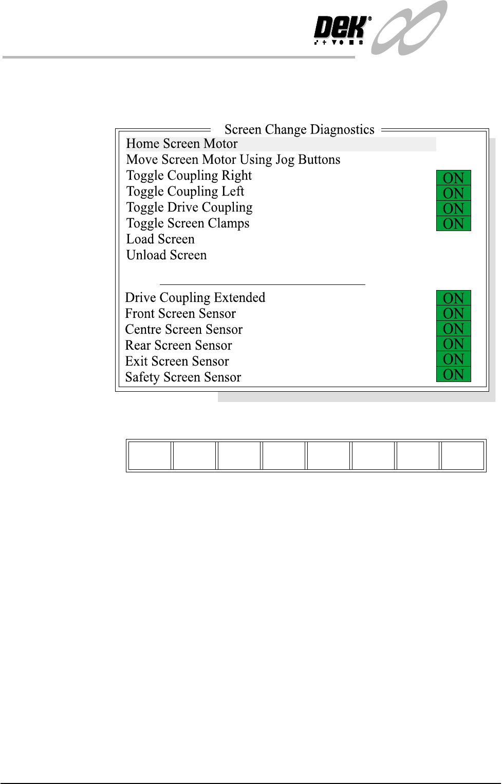
Screen Change Selecting this diagnostics module opens the following window:
The menu bar changes displaying the following:
Next / Previous keys move the highlight bar up and down the list of selectable
diagnostic functions.
Run Diagnost activates the diagnostic function, as selected by the highlight bar.
Exit returns operation to the module diagnostics page.
Home Screen Motor Selecting this diagnostic function drives the screen motor to its home position,
as set by its home sensor.
Move Screen Motor
Using Jog Buttons
Selecting this diagnostic function drives the screen motor using the jog buttons.
The right jog button drives the screen motor forward and the left jog button
drives it to the rear, stopping immediately the button is released.
Toggle Coupling
Right
Selecting this diagnostic function alternately energizes and de-energizes the
drive coupling right solenoid, displaying On when energized and Off when de-
energized.
Toggle Drive
Coupling
Selecting this diagnostic function alternately energizes and de-energizes the
drive coupling left solenoid, displaying On when energized and Off when de-
energized.
Run
Diagnost
Next Previous Exit