Infinity DI.pdf - 第9页
1.4 Infinity Dual Imag e Manual Chapter Issue 4 Aug 01 INFINITY TECHNIC AL RE FERENCE PNEUMA TIC SC HEMATI C PNEUMATIC SCHEMAT IC Figure 1-3 Pneumatic Schematic
INFINITY
TECHNICAL REFERENCE
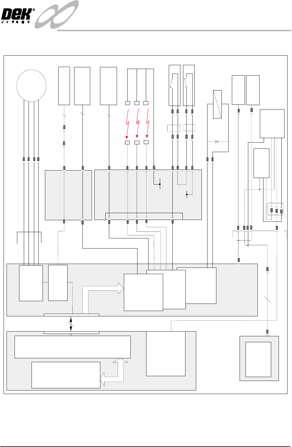
ELECTRICAL SCHEMATIC
Chapter Issue 4 Aug 01 Infinity Dual Image Manual 1.3
ELECTRICAL SCHEMATIC
Figure 1-2 Electrical Schematic
X13
Machine Controller
CAN Bus
Machine PC
100
Way
Screen Home
Processor
NextMove
ISA Bus
Breakout Board D
Screen
Load
Stepper
Motor 13M1
Motor B-2
Motor B+2
Motor A-2
Motor A+2
M19PL37
3
3
4
DPL1
Screen Home
13SE05
Screen in Transit
'Rear'
9SE19
DPL6
DPL8
DPL2
IN1
Breakout Board F
Screen in Transit
'Front'
9SE18
FPL3
FPL1
IN7
IN 6
Screen at Front
12V
Screen at Centre
IN 5
12V
Screen at Rear
IN 4
12V
12V
FPL4
FPL5
R/H Rear Coupling Extended
13SE08
L/H Rear Coupling Extended
13SE09
IN3
IN8,9
2
0v
X11
MultiMove
X12
X7
4 Channel RS232
Comms Expansion
Screen Clamps
(6 positions)
Product
Sensor
Board Present
Sensor
Rear Service Panel
6SK20
6PL18
6PL19
6SK21
6PL22
Product
Bar Code
Reader
16SK07
+
16SK18,19,20
Source 0
0v
+
-
Stepper Drive
X6
Channel 2
Multiplexer
MUX4
Pa r t D C
PSU
6PL17(part of)
6PL17(part of)
Trigger
Bar Code
Scan
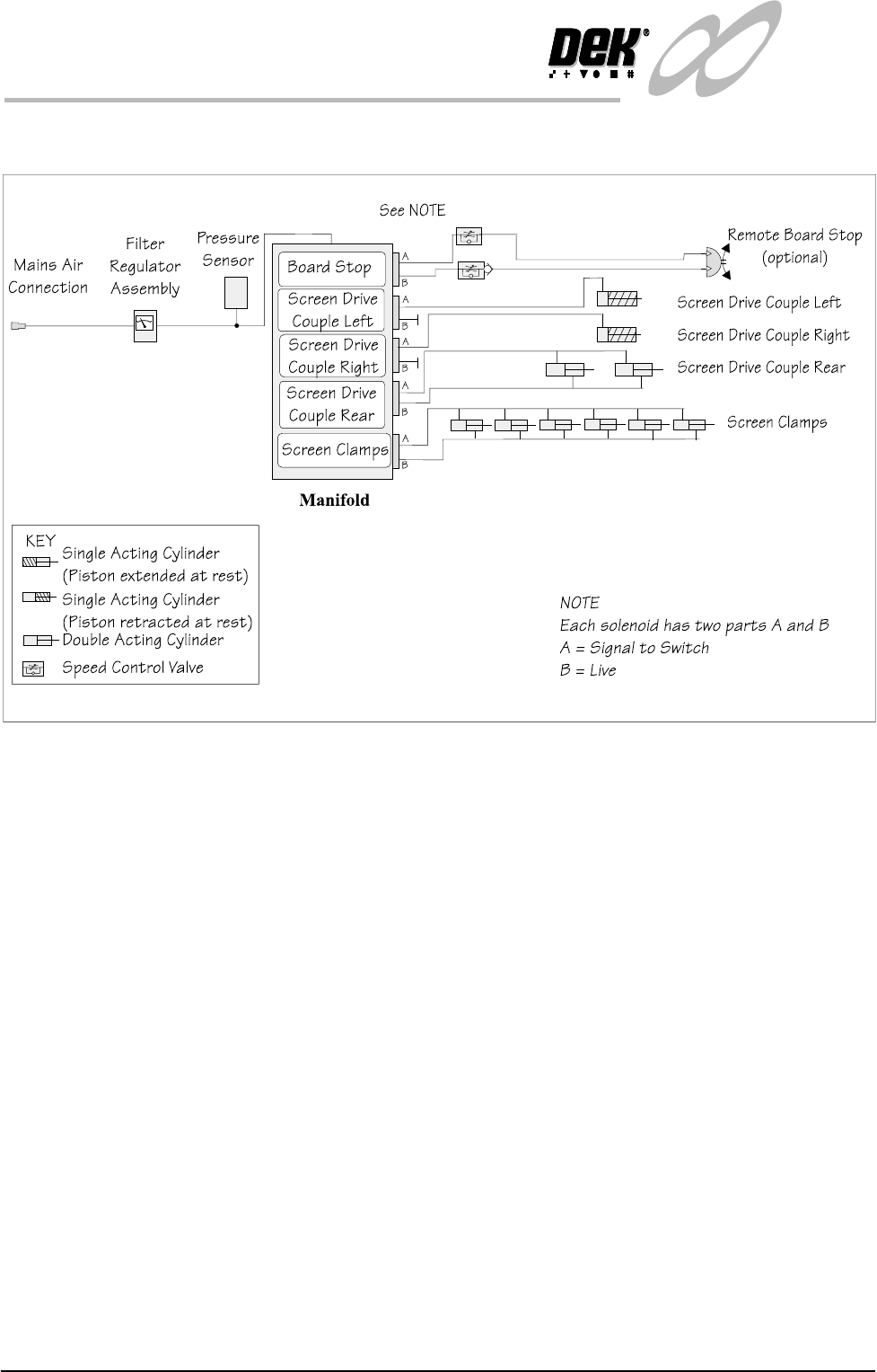
1.4 Infinity Dual Image Manual Chapter Issue 4 Aug 01
INFINITY
TECHNICAL REFERENCE
PNEUMATIC SCHEMATIC
PNEUMATIC SCHEMATIC
Figure 1-3 Pneumatic Schematic
INFINITY
TECHNICAL REFERENCE
MECHANICAL DETAIL
Chapter Issue 4 Aug 01 Infinity Dual Image Manual 1.5
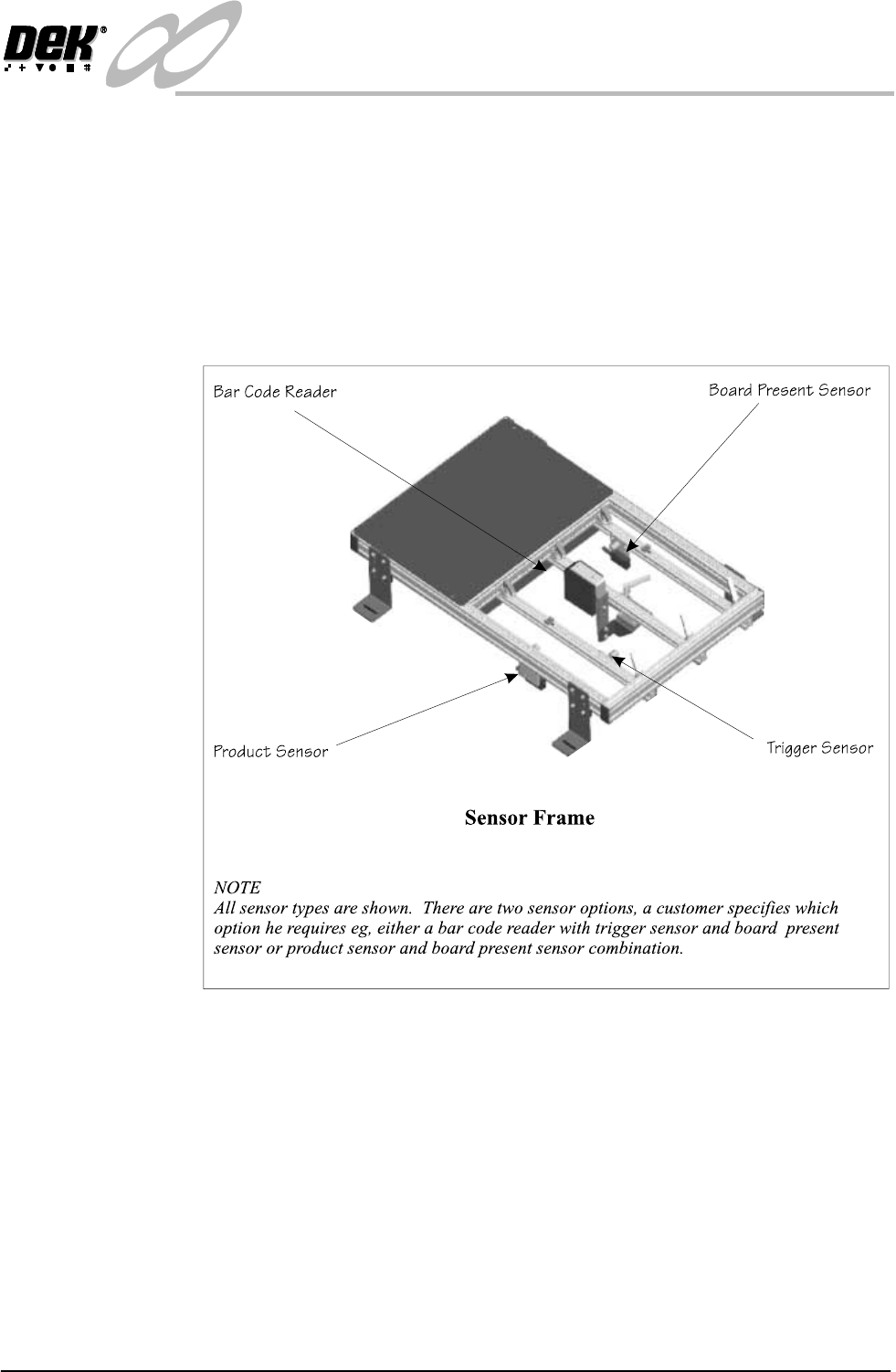
MECHANICAL DETAIL
Sensor Frame A sensor frame is provided at the input conveyor, this gives support for the
respective input sensors. The frame is supplied as specified for left or right hand
input conveyor systems. If the process is altered e.g., the printing machine is
repositioned and the input conveyor is changed-over, then the sensor positions
need to be ‘mirrored’ on the frame. The product to be printed may vary in size
from one print run to the next, the frame can be quickly reconfigured to
accommodate the different board widths.
To adjust the sensor frame see Adjustments and Settings later in this chapter.
Figure 1-4 The Sensor Frame for the Left Hand Conveyor Configuration