00197288-02_AI_TBO_SX12_V2_DE_EN - 第49页
3 Installation 3.4 Converting the Clamping Plate Assembly Instructions / Montageanleitung SIPLACE SX1/SX2 V2 Thick Board Option Option Dicke Leiterplatte 02/2019 49 3.4 Converting the Clamping Plate Overview Fig.14: Cla…
3 Installation
3.3 Lowering the Conveyor
48 Assembly Instructions / Montageanleitung SIPLACE SX1/SX2 V2 Thick Board Option Option Dicke Leiterplatte
02/2019
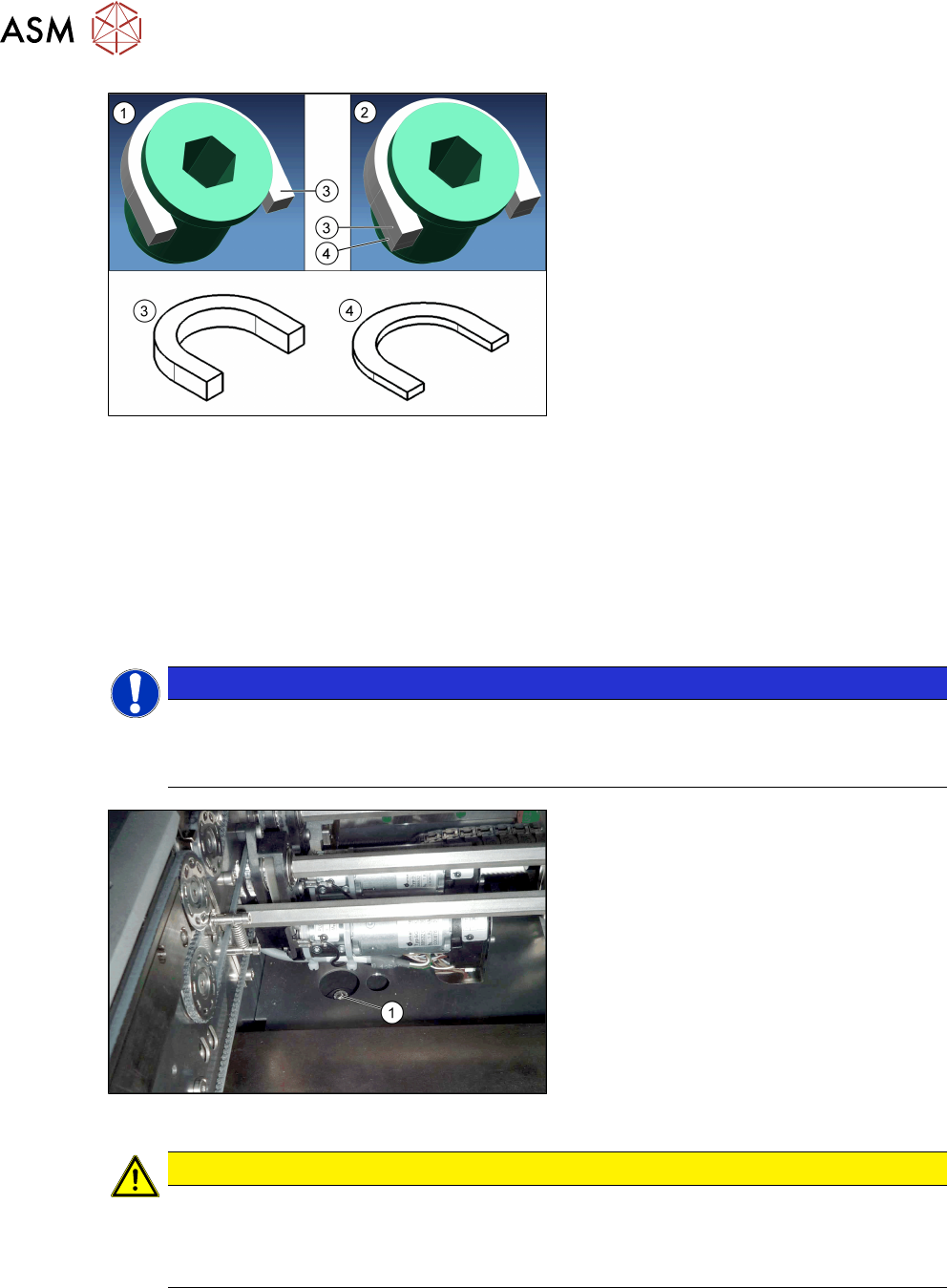
Fig.12: Grub screw with distance plates
1. Grub screw with collar and a distance
plate (5mm) for the standard height
2. Grub screw with collar and two dis-
tance plates (5mm and 2mm) for the
"Thick Board "option.
3. Horseshoe-shaped 5 mm distance
plate [03104924‑xx] (for standard and
"Thick Board" option)
4. Horseshoe-shaped 2mmm distance
plate [03104937‑xx] (for "Thick Board"
option only)
► Place one horseshow-shaped 5mm distance plate (standard height) und one horseshoe-
shaped 2mm distance plate (for "Thick Board" option) under the collar of each of the all set-
ting screws.
Now tighten all setting screws until they only just clamp the distance plates but do not yet al-
ter the conveyor height.
► Now turn all setting screws one rotation more so that the conveyor is raised equally at all
points.
Repeat this until the setting screws are tight.
NOTICE
Direction of rotation
► Turn the setting screws clockwise to move the conveyor upwards.
► Turn the setting screws anticlockwise to move the conveyor downwards.
Fig.13: Fastening screw
► Insert the new, long fastening
screws(1) incl. old washers and tighten
these.
Before you insert the screws, clean the
area around them. Even minor contam-
ination can influence the conveyor
height.
CAUTION
Have you fitted everything?
► Make sure that all eight U-shaped distance plates (4 x 2mm and 4x 5mm) are fitted.
If these are not all fitted, the machine could be damaged due to the conveyor being
too high.
3 Installation
3.4 Converting the Clamping Plate
Assembly Instructions / Montageanleitung SIPLACE SX1/SX2 V2 Thick Board Option Option Dicke Leiterplatte
02/2019
49
3.4 Converting the Clamping Plate
Overview
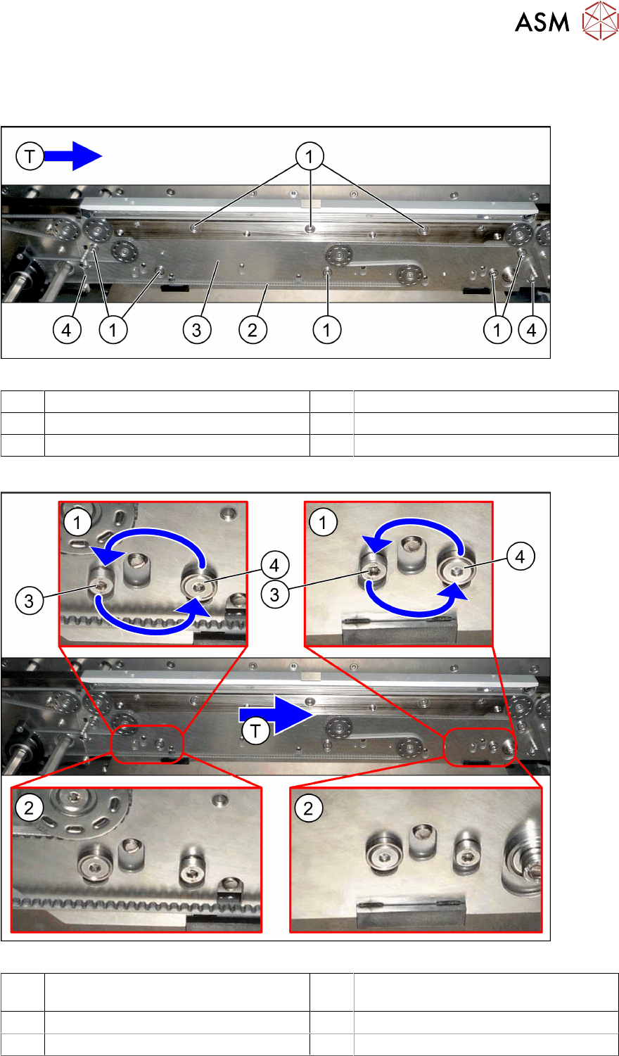
Fig.14: Clamping plate overview
1 Fastening screws (8x) for clamping plate 2 Toothed belt
3 Clamping plate 4 Springs (2x)
T Transport direction
Conversion
Fig.15: Converting the clamping plate
1 Clamping plate before conversion,
without the "thick board" option.
2 Clamping plate after conversion, with the
"thick board" option.
3 Retaining screw for sliding disk 4 Screw with bushing (guidance)
T Transport direction
3 Installation
3.5 Converting the Clamping Rail
50 Assembly Instructions / Montageanleitung SIPLACE SX1/SX2 V2 Thick Board Option Option Dicke Leiterplatte
02/2019
► Some conveyors do not have the "Thick Board" option already prepared on the clamping
plate. In these cases, you need to insert the screw (3) with the sliding disk behind it onto the
clamping plate. As the sliding disk is located between the clamping plate and the conveyor
rail, you need to dismantle the clamping plate for this. Read the relevant section of the service
manual for your machine.
You also need to observe the following steps when fitting the clamping plate.
The following steps must be performed in each case. If you have removed the clamping plate,
observe these steps while fitting the clamping plate again.
► Remove the top retaining screw on the spring. Make sure that you do not lose the spring and
the bushing on the screw. When you refit them, check the bushing for correct orientation. Re-
peat this step for the second clamping plate spring.
The screws(3) and(4) each have a sliding disk between the conveyor rail and the clamping plate.
To prevent these sliding disks from slipping, press the clamping plate slightly against the conveyor
rail during the following replacement work.
► Exchange the position of the screws(3) and(4) (incl. bushing).
NOTICE
Travel range
When using boards with standard thickness, the clamping plate is pressed against the
clamping rail by the lifting table when operated while empty i.e without a board. This is the
highest position which can be reached. However, since neither the lifting table nor the
clamping plate can reach the maximum of 8.5 mm required for the thick board, this travel
range needs to be limited with the screws(4). These screws define the top stopper in case
a board which is too thin (<2mm) is moved in.
► Repeat these steps for all conveyor rails.
3.5 Converting the Clamping Rail
► Remove the old clamping rail and fit the new "clamping rail for thick board SX1a assem-
bly" [03099567‑xx]. Read the relevant section of the service manual for your machine.
NOTICE
Converting the clamping rail
► The procedure is identical for removal and installation of the old and new clamping
rails.
► The new clamping rail protrudes slightly above the conveyor side.
► Repeat these steps for all conveyor sides.