00198328-01_AI_Basic Pack Vakuum Tooling_TX_DE_EN.pdf - 第36页
4 Anhang 4.4 Übersicht 36 Montageanleitung / Assembly Instructions SIPLACE TX-Serie Basic Pack Vacuum Tooling 07/2017 4.4 Übersicht
4 Anhang
4.1 Auszüge aus der Serviceanleitung
Montageanleitung / Assembly Instructions SIPLACE TX-Serie Basic Pack Vacuum Tooling 07/2017 35
4 Anhang
4.1 Auszüge aus der Serviceanleitung
Die folgenden Kapitel sind Auszüge aus der Serviceanleitung Ihrer Maschine. Dort finden Sie ggf.
weitere Informationen.
●
Serviceanleitung SIPLACE TX-Serie [DE:00198149‑xx] [EN:00198150‑xx]
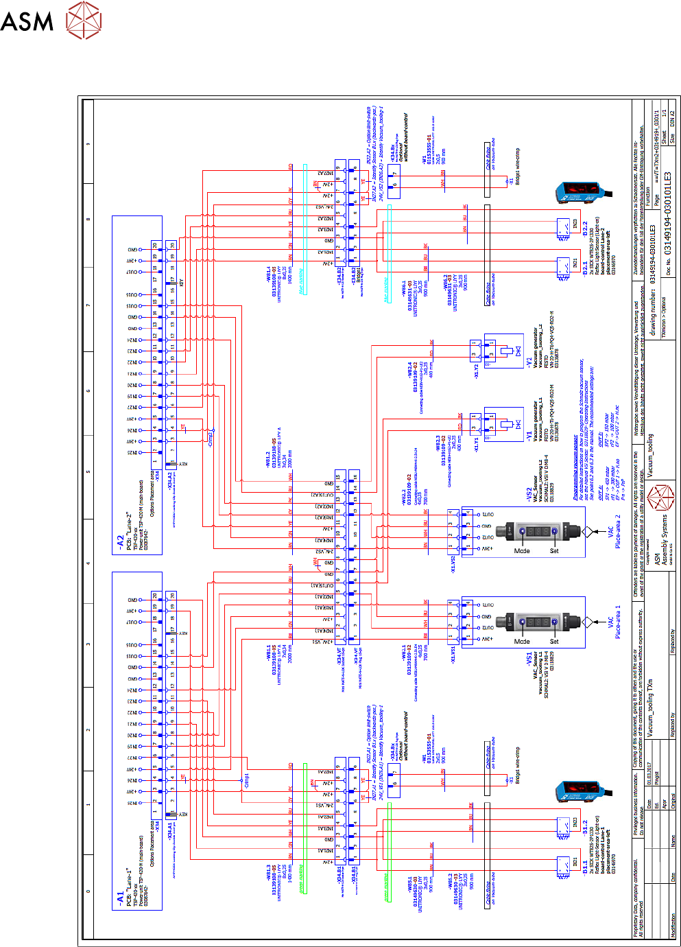
4.2 Stromlaufpläne
Weitere Informationen finden Sie in der Wirkschaltplanmappe:
●
Wirkschaltplanmappe SIPLACE TX-Serie (bis Nr. 499) [DE+EN:00197933-xx]
●
Wirkschaltplanmappe SIPLACE TX-Serie (ab Nr. 500) [DE+EN:00198274-xx]
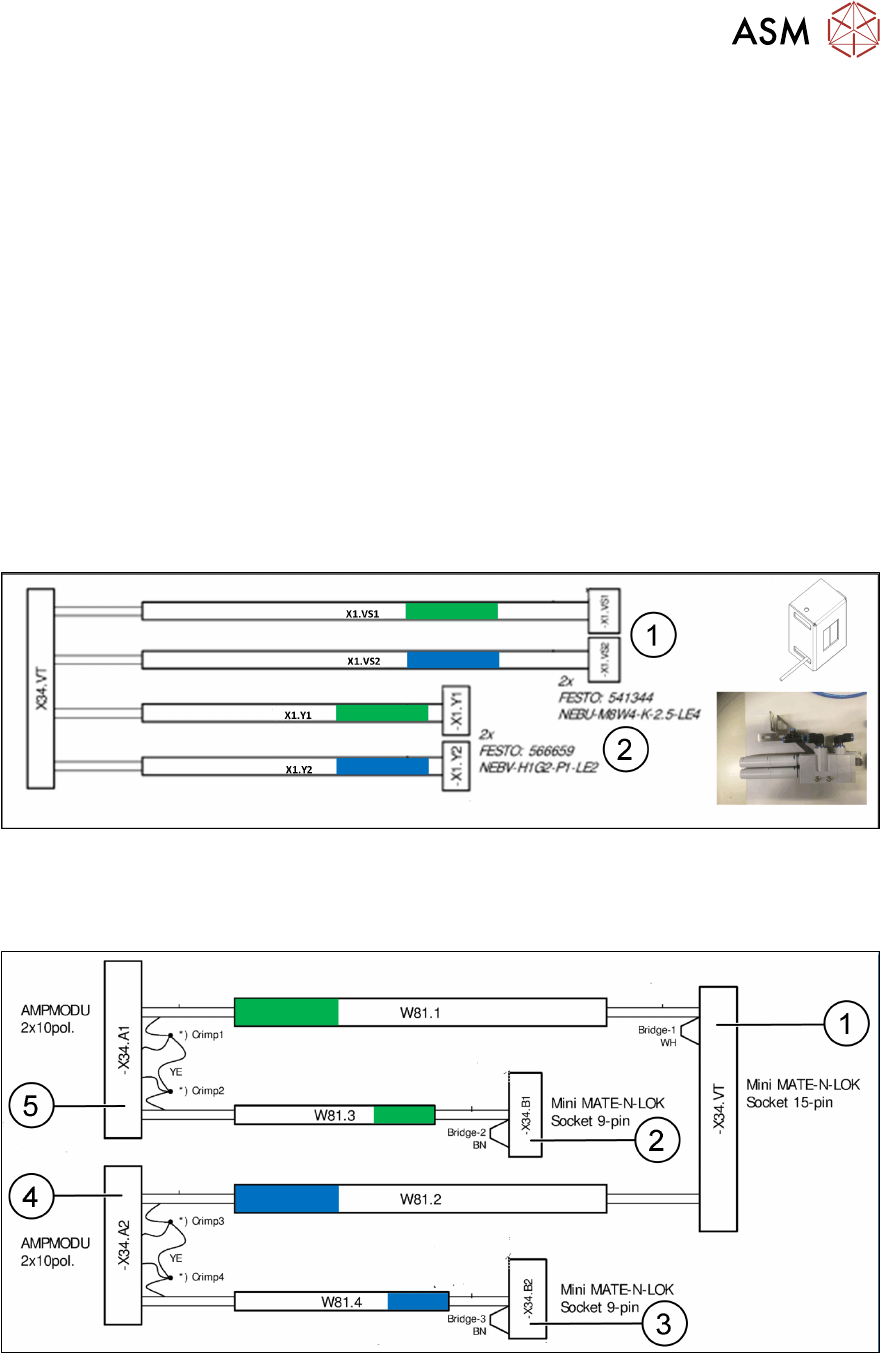
4.3 Überblick Kabel
4.3.1 Stecker Stellplatz 2
1. Stecker Vakuumschalter an der Eckverkleidung
2. Stecker Ventile Vakuumerzeugung
4.3.2 Stecker X34 Transportsteuerung
1. Buchse Stellplatz 2 an der Seite
2. Buchse Spur 1 im Blech unter der Transportspur 1
3. Buchse Spur 2 im Blech unter der Transportspur 2
4. Stecker X34 Transportsteuerung Spur 2
5. Stecker X34 Transportsteuerung Spur 1
4 Anhang
4.4 Übersicht
36 Montageanleitung / Assembly Instructions SIPLACE TX-Serie Basic Pack Vacuum Tooling 07/2017
4.4 Übersicht

37Montageanleitung / Assembly Instructions SIPLACE TX-Serie Basic Pack Vacuum Tooling 07/2017
1 Introduction.. 39
1.1 Safety Instructions.. 39
1.1.1 Conventions for the Use of Safety Instructions and Symbols.. 39
1.1.2 Safety Instructions for Working with Strong Magnetic Fields.. 40
1.1.3 Safety Instructions for the Power Supply (With SMPS).. 40
1.1.4 Safety instructions for the compressed air supply.. 42
1.1.5 Safety Instructions for the Gantry.. 42
1.1.6 Safety Instructions on Hazardous Materials.. 42
1.2 Preparatory Work..... 43
1.3 Other Instructions.. 45
1.3.1 Environmentally-Friendly Disposal of Materials and Components.. 45
1.3.2 Use of Original SIPLACE Accessories and Spare Parts.. 45
1.3.3 ESD Guidelines.. 45
1.3.3.1 Definition of ESD.. 45
1.3.3.2 Important Measures to Protect Against Static Charging.. 45
1.3.3.3 Handling ESD Modules.. 45
1.3.3.4 Measurements and Modifications to ESD Modules.. 46
1.3.3.5 Dispatching ESD Modules.. 46
1.3.4 Validity of Document.. 46
1.3.5 Release History.. 46
1.4 Staff Qualifications and Training.. 47
2 Brief Description.. 49
2.1 Product Description.. 49
2.2 Prerequisites.. 49
2.3 Scope of Delivery.. 50
2.4 Tools and Equipment Required.. 52
2.5 Required Working Time.. 52
3 Installation.. 53
3.1 Preparatory Steps.. 53
3.2 Assembly.. 54
3.3 Final Work.. 57
3.3.1 Settings in the Vacuum Switch.. 59
3.3.1.1 Factory Settings.. 60
3.3.1.2 Setting Switching Point 2 as Normally Open.. 61
3.3.1.3 Setting Switching Point 1.. 62
3.3.1.4 Setting Hysteresis Switching Point 1.. 63
3.3.1.5 Setting Switching Point 2.. 64
3.3.1.6 Setting Hysteresis Switching Point 2.. 65
4 Appendix.. 67
4.1 Excerpts from the Service Manual.. 67
4.2 Circuit Diagrams.. 67
4.3 Cable Overview.. 67
4.3.1 Connectors Location 2.. 67
4.3.2 X34 Connectors Conveyor Control.. 67
4.4 Overview.. 68