00198328-01_AI_Basic Pack Vakuum Tooling_TX_DE_EN.pdf - 第54页
3 Installation 3.2 Assembly 54 Montageanleitung / Assembly Instructions SIPLACE TX-Serie Basic Pack Vacuum Tooling 07/2017 3.2 Assembly ► Fit the angle with the maintenance unit (1). ► Connect the pneumatic hose for the …
3 Installation
3.1 Preparatory Steps
Montageanleitung / Assembly Instructions SIPLACE TX-Serie Basic Pack Vacuum Tooling 07/2017 53
3 Installation
3.1 Preparatory Steps
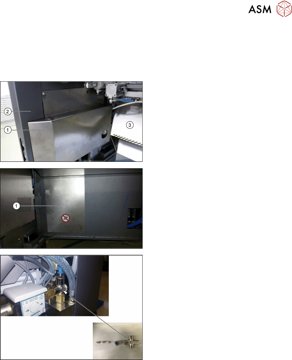
► Move the component trolley at location 2 out of the machine.
► Switch off the machine, disconnect it from the air supply and the power supply.
► Remove the left slide plate (1), the corner cover
(2) and the waste tape chute (3).
► Remove the cover plate (1) at the machine base
of location 2.
► If a T-piece is installed in the control block, re-
place it with a crosspiece.
► Fit the FESTO connection on the top output.
► Run the PUN10 pneumatic hose via the opening
inside the machine through the side panel to the
crosspiece.
► Connect the PUN10 pneumatic hose to the
crosspiece.
3 Installation
3.2 Assembly
54 Montageanleitung / Assembly Instructions SIPLACE TX-Serie Basic Pack Vacuum Tooling 07/2017
3.2 Assembly
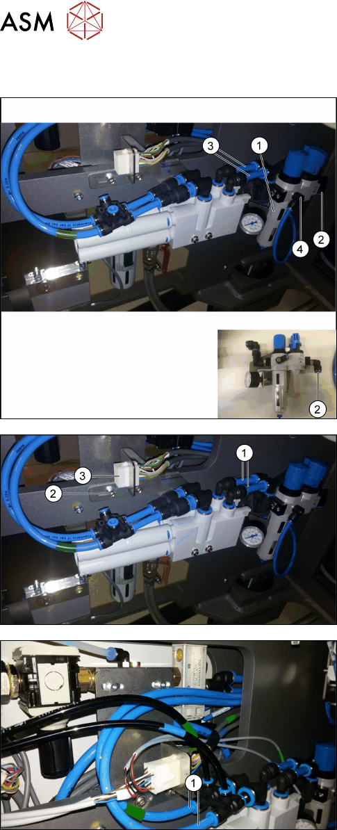
► Fit the angle with the maintenance unit (1).
► Connect the pneumatic hose for the compressed
air supply of the maintenance unit (2).
► Connect the two PUN 10 - 70 mm pneumatic
hoses (3) to the maintenance unit.
► Connect the manometer output (4) to the mano-
meter: Connect the PUN 6 - 300 mm pneumatic
hose to the manometer output (4). Connect the
hose from the back to the manometer beside (1).
► Connect the vacuum unit to the maintenance unit
via the two pneumatic hoses (1).
► Fit the angle with the vacuum unit (2) at the side
wall as displayed in the picture.
► Pull the [03139108-04] cable through the opening
inside the machine through the side panel.
► Fit the connector (3) in the bracket (connector
X34.VT with cable [03139108-04]).
► Connect the 2 tied PUN 8 - 2800 mm pneumatic
hoses (1) to the T-pieces of the vacuum unit. The
ends shall then be drawn through the machine to
below the conveyor unit, please refer to the sub-
sequent illustrations and description.
3 Installation
3.2 Assembly
Montageanleitung / Assembly Instructions SIPLACE TX-Serie Basic Pack Vacuum Tooling 07/2017 55
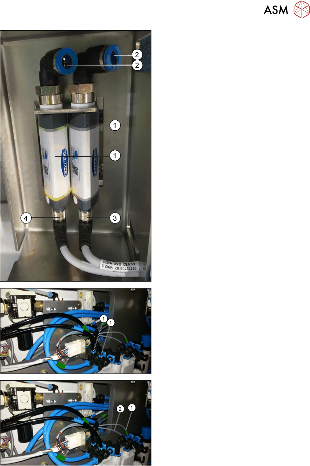
► Fit the two vacuum switches (1) into the plate
supports.
► Connect the two PUN 6 - 800 mm pneumatic
hoses to the opening (2) at the vacuum switch
(1). Observe the green marking for lane 1 and the
blue marking for lane 2!
► Connect the X1.VS2 cable (3) to the right va-
cuum switch.
► Connect the X1.VS1 cable (4) to the left vacuum
switch.
► Pull down the pneumatic hoses and the cables
through the corner cover.
► Connect the two pneumatic hoses to the vacuum
unit (1). Observe the green marking for lane 1
and the blue marking for lane 2!
► Connect the X1.Y1 cable (1) to the left valve of
the vacuum unit (green marking for lane 1).
► Connect the X1.Y2 cable (2) to the right valve of
the vacuum unit (blue marking for lane 2).