CP6的IO代码.pdf - 第163页
Notes: Part 5 Chapter 1 Placing Head Edition 1.0 5-1-4 CP-6 Series Mechanical Reference
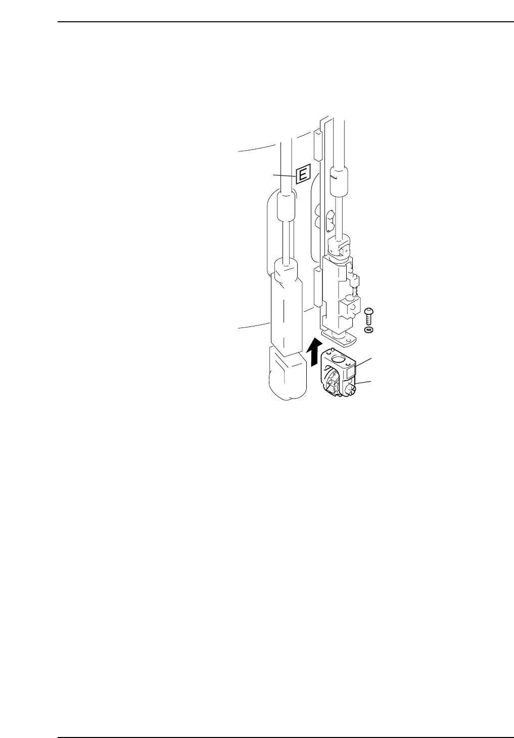
Installation
Install the nozzles such that the nozzle numbers match the seal numbers affixed to the
aluminum drums. The seal attached to the aluminum drum indicates the placing head
facing to the right so be sure not to mistake the wrong placing head.
Sticker
Sticker
E
Holder
CP6M5003
Part 5 Chapter 1 Placing Head
Edition 1.0 5-1-3 CP-6 Series Mechanical Reference

Notes:
Part 5 Chapter 1 Placing Head
Edition 1.0 5-1-4 CP-6 Series Mechanical Reference
Part 5 Chapter 2 Cam Box
Edition 1.2 5-2-1 CP-6-series Mechanical Reference
2. Cam Box
2.1 Synchronizing the Cam Axes
In the cam box, two cam shafts and 2 sets of index units support a number of cams. If
there is a shift or slippage between these cams, parts may not be placed. The following
procedures explain how to synchronize the cam axes.
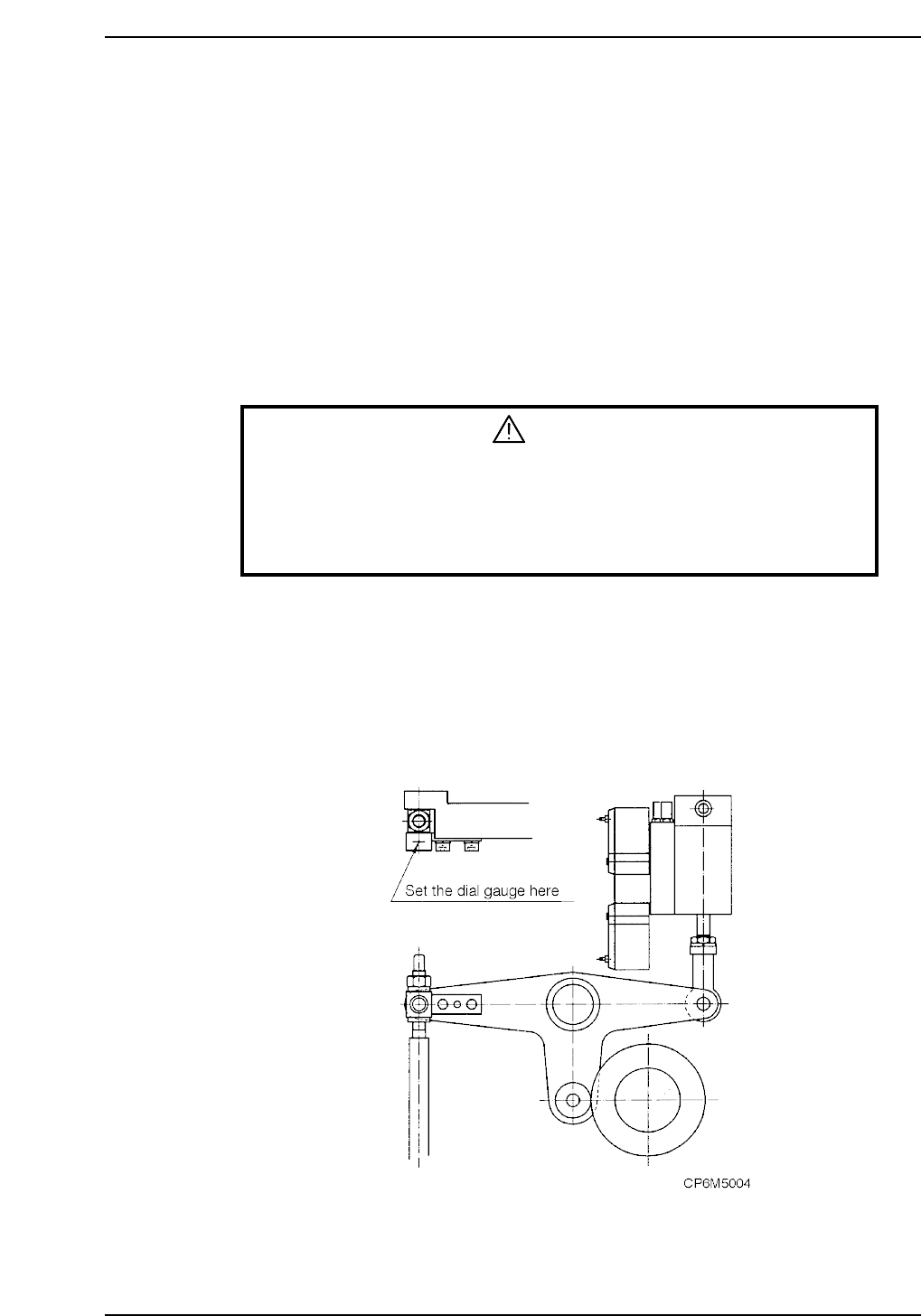
The term "stationary point" refers to the position where the cam lever stops.
The stationary point can be confirmed by setting the dial gauge on the cam lever.
Adjustment procedure
1. When making these adjustments, make sure that the power is turned off.
WARNING
• Always be sure to cut off the main power before carrying out any
work.
• Exercise extreme caution when working on the machine if the cam is
not at its origin (0 deg.). Recoil of the cam axis can endanger the
operator.
2. Remove all nozzle units (nozzle holders).
3. Confirm that the timing belts in the cam box are set at the right tension.
Refer to section 2.2 “Timing Belt Tension Adjustment (Cam Box)” of this chapter.
4. Cam A position check
i) Check the cam position using the station 11 nozzle up/down lever.
ii) With the cam at 0°, set the dial gauge on the cam lever. At this time, confirm
that the cam roller is at the farthest point