CP6的IO代码.pdf - 第165页
Part 5 Chapter 2 Cam Box Edition 1.2 5-2-2 CP-6-series Mechanical Reference iii) Using the handle, turn the cam counterclockwise (0°-› 360°). Check to see when the dial gauge begins to move from 0. If the dial gauge begi…
Part 5 Chapter 2 Cam Box
Edition 1.2 5-2-1 CP-6-series Mechanical Reference
2. Cam Box
2.1 Synchronizing the Cam Axes
In the cam box, two cam shafts and 2 sets of index units support a number of cams. If
there is a shift or slippage between these cams, parts may not be placed. The following
procedures explain how to synchronize the cam axes.
The term "stationary point" refers to the position where the cam lever stops.
The stationary point can be confirmed by setting the dial gauge on the cam lever.
Adjustment procedure
1. When making these adjustments, make sure that the power is turned off.
WARNING
• Always be sure to cut off the main power before carrying out any
work.
• Exercise extreme caution when working on the machine if the cam is
not at its origin (0 deg.). Recoil of the cam axis can endanger the
operator.
2. Remove all nozzle units (nozzle holders).
3. Confirm that the timing belts in the cam box are set at the right tension.
Refer to section 2.2 “Timing Belt Tension Adjustment (Cam Box)” of this chapter.
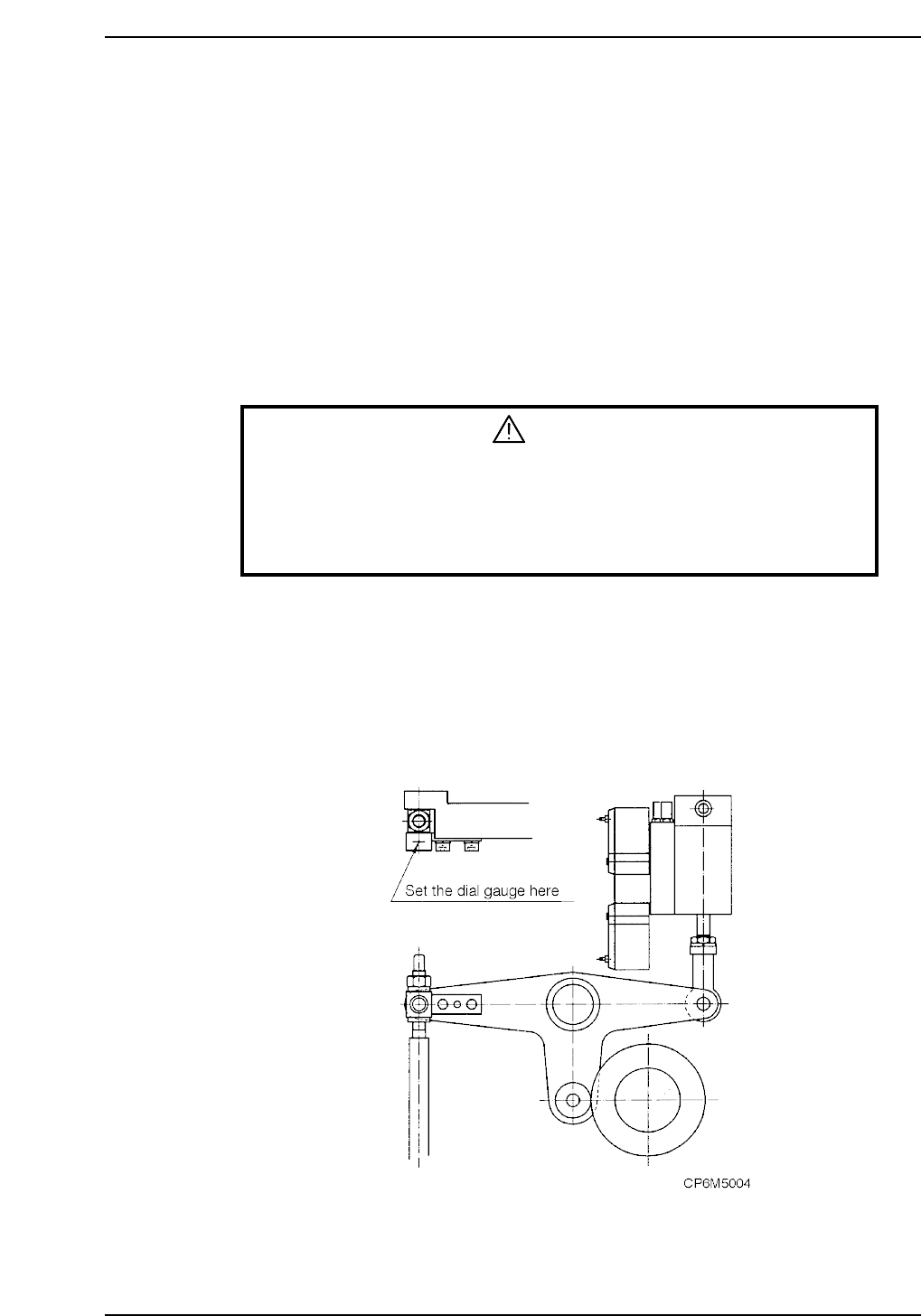
4. Cam A position check
i) Check the cam position using the station 11 nozzle up/down lever.
ii) With the cam at 0°, set the dial gauge on the cam lever. At this time, confirm
that the cam roller is at the farthest point
Part 5 Chapter 2 Cam Box
Edition 1.2 5-2-2 CP-6-series Mechanical Reference
iii) Using the handle, turn the cam counterclockwise (0°-› 360°). Check to see
when the dial gauge begins to move from 0. If the dial gauge begins to move
at 53°, (CP 6-4000 types)/75° (CP 6-5000 types) the cam position is correct. If
it is hard to see the movement of the dial gauge , continue until the gauge
moves 0.2 mm. If it moves at 68°, it is correct. (For CP 6-4000 type)
5. Cam B position check
i) Check the cam position using the station 1 waste tape cutter lever.
ii) Using the handle, turn the cam to 203°. At this point set the dial gauge on the
waste tape cutter.
iii) If the cam is at its lowest point at 203°, the cam gauge is correctly installed.
6. Turn cam axis B to 0°. At this time, if cam axis A is also 0°, cam axis A and cam
axis B are synchronized. Cam axis offset must be within 2°.
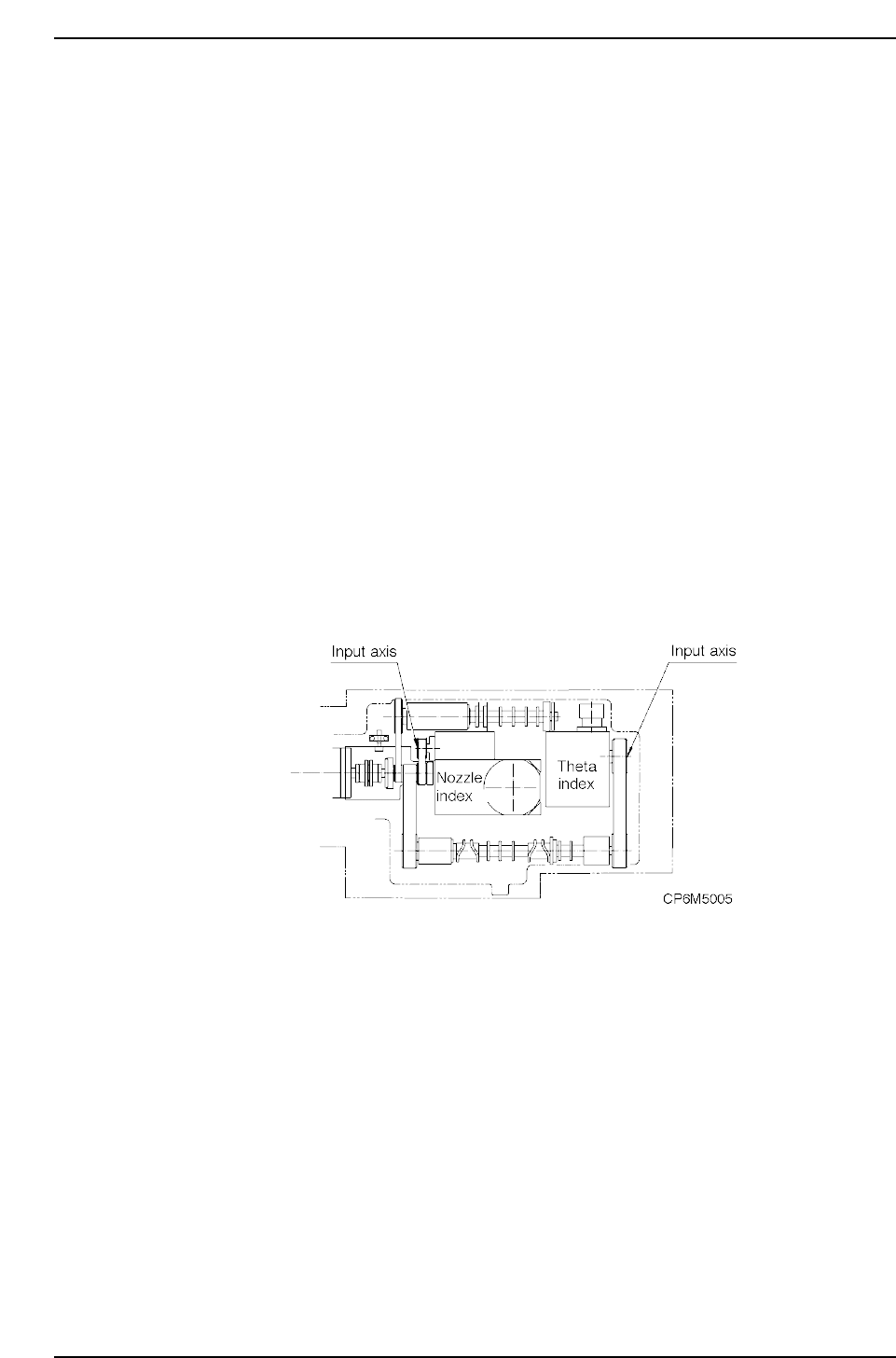
7. The nozzle index unit begins to turn after 253°. Using the handle, turn to 253° and
stop. At this position, turn the nozzle index unit input axis until it begins to
engage. At the position where it engages, set the mechanical locking ring to lock
this position.
8. The theta index unit begins to turn after 299° (4000 type)/293° (5000 type). Using
the handle, turn to 299°/293° and stop. At this position, turn the theta index unit
input axis until it begins to engage. At the position where it engages, set the
mechanical locking ring to lock this position.
Note: When synchronizing the cam axes, be careful because the index unit sometimes turns
unpredictably.
Part 5 Chapter 2 Cam Box
Edition 1.2 5-2-3 CP-6-series Mechanical Reference
2.2 Timing Belt Tension Adjustment (Cam Box)
WARNING
• Always be sure to cut off the main power before carrying out any
work.
• Exercise extreme caution when working on the machine if the cam is
not at its origin (0 deg.). Recoil of the cam axis can endanger the
operator.
<4000 Type>
There are four timing belts in the cam box. With a finger flick the center of the timing
belt to start it oscillating. Measure the oscillation with a frequency meter and compare
the readout with the stipulated frequency values. The belt's frequency of oscillation can
be adjusted using the jack bolt.
Adjustment procedure
First, adjust the tension of the belt (b) between the central axis and nozzle index unit.
Through using the adjustment bolt and moving the central axis, the tension changes. At
this time, make sure that there is no tension on belts (a) and (d).
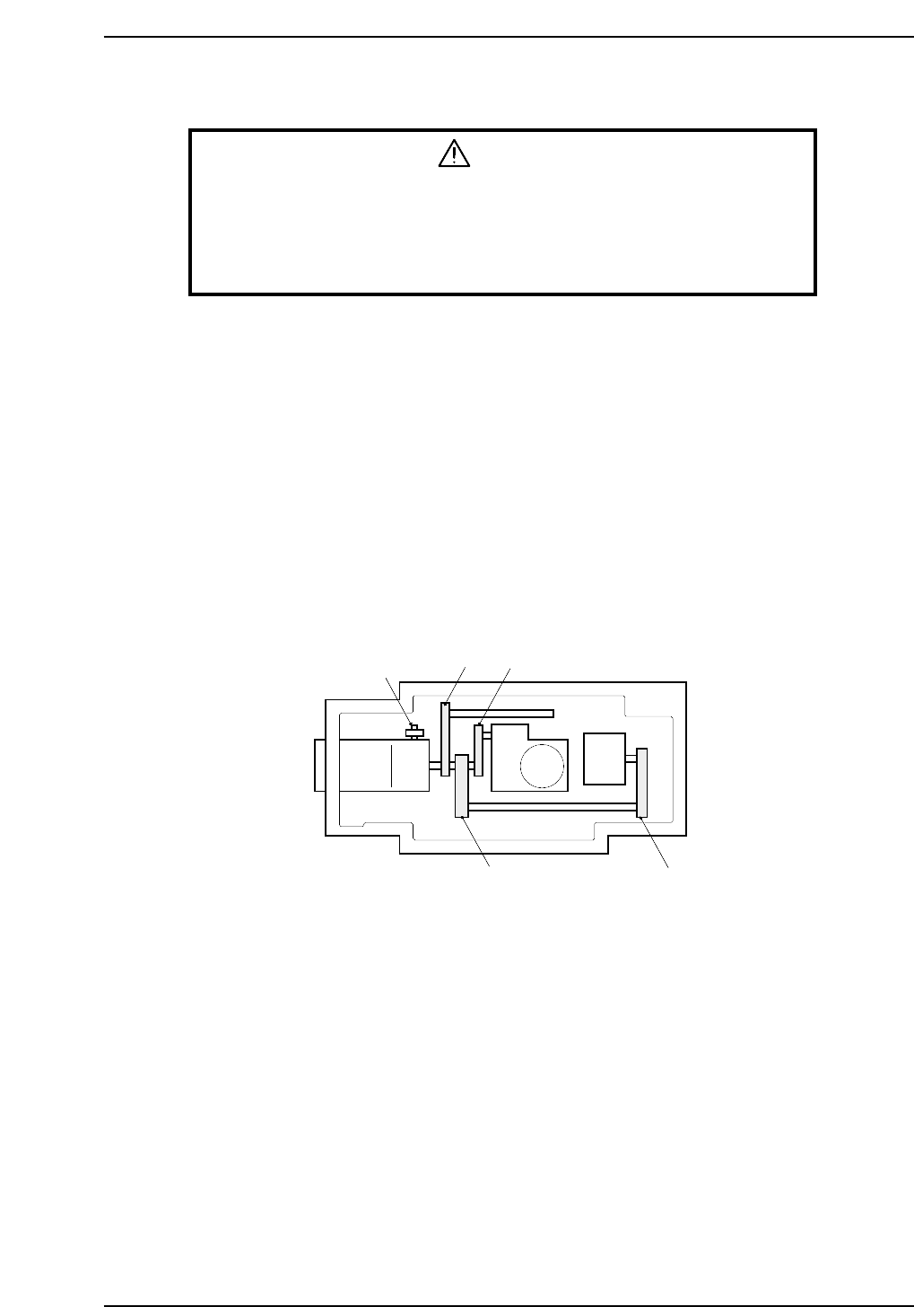
Next, adjust belts (a), (c), and (d) using the tension pulley. Refer to figure below for belt
location and the figure on the following page for tension values.
Motor
Adjusting bolt
(a)
(b)
(c)
(d)
CP6M5006