CP6的IO代码.pdf - 第227页
Part 5 Chapter 5 Servo Adjustments Edition 1.0 5-5-4 CP-6 Series Mechanical Reference 5.2 Servo Adjustments The following section discusses CP-6 series servo amplifier adjustments. The two adjustments to be discussed are…
Part 5 Chapter 5 Servo Adjustments
Edition 1.0 5-5-3 CP-6 Series Mechanical Reference
Servo Amplifiers
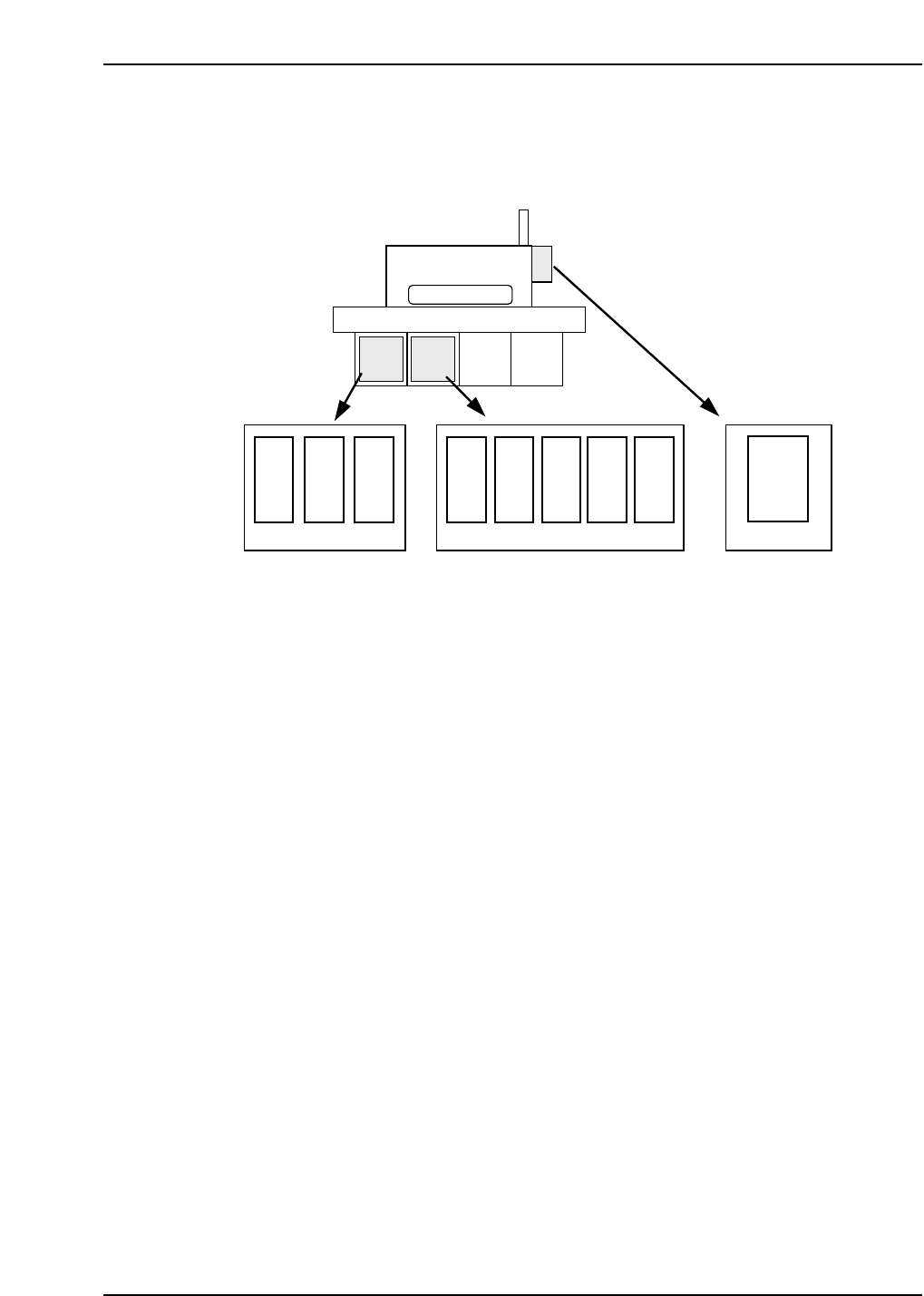
The amplifier takes instructions from the servo card and provides the power to the
motors. This controls the actual movement of the motor (via the motor windings). The
locations of each are depicted below.
Servo Motors
Each servo motor found on FUJI machines need to be precisely controlled. In order to
control these motors, a monitoring device called a “pulse generator” or “encoder” is
mounted to the motor shaft. The encoder monitors the rotation of the motor shaft by
tracking a circular disk attached to that shaft. A fixed number of holes are cut into this
disk which allows an infrared LED to shine through these holes. In this way the encoder
can track shaft motion. The number of holes cut into the disk determines the encoders’
resolution. Also, on one point of the encoder disk, a single hole is present which sends a
“home” pulse signal once per revolution.
The servo amplifier judges the rotational direction by comparing phase A with phase B,
to see which phase is leading the other.
Distance traveled is determined by the number of pulses received.
Speed is determined by the frequency of the pulses that are received.
X
Y
CAM
D2
D1
Z
FR
F θ
CP-6
θ
NC
Nozzle
change
Servo box 1 Servo box 2
Operation box 1
CP6M5076
Part 5 Chapter 5 Servo Adjustments
Edition 1.0 5-5-4 CP-6 Series Mechanical Reference
5.2 Servo Adjustments
The following section discusses CP-6 series servo amplifier adjustments. The two
adjustments to be discussed are:
• Zero adjustments
• Gain adjustments
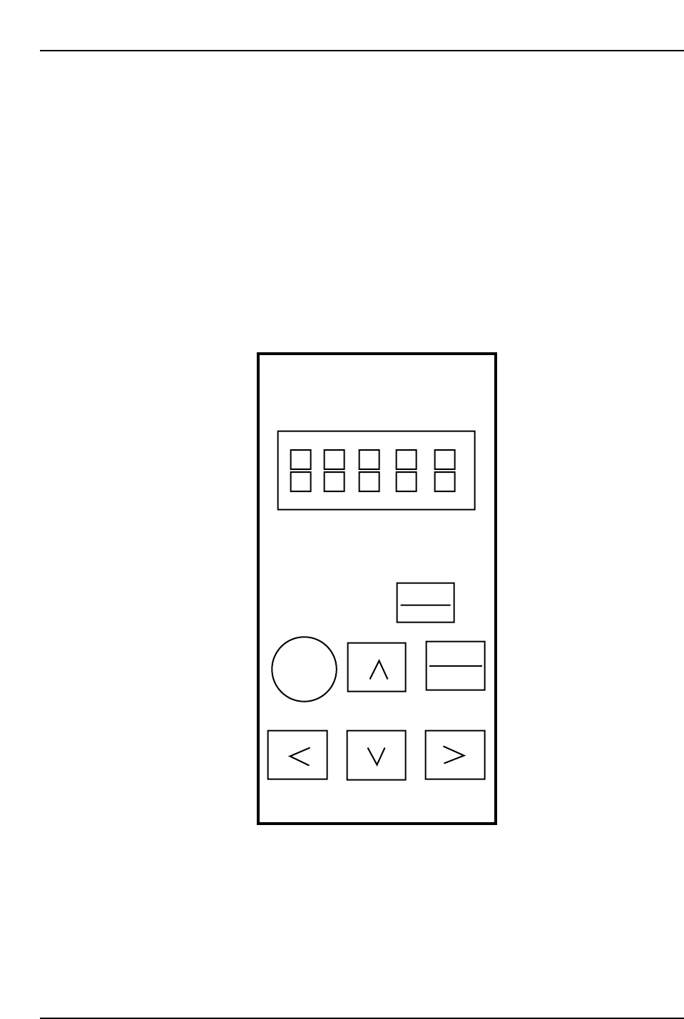
Performing zero adjustments on CP-6 series amplifiers will require the use of a digital
operator.
Note: Manual zero adjustments will be necessary for analog input amplifiers, D1 and D2. For X,
Y, Z, FRQ, FQ and NC amplifiers on the CP643E and CP643ME machines, adjustments
are performed on the amplifier itself. For all other amplifiers the digital operator below is
used.
RESET
Servopack
Digital
Operator
Jusp-0p02A
DSPL
SET
ALARM
JOG
SVON
DATA
ENTER
Yaskawa
Digital Operator
CP6M5077
Part 5 Chapter 5 Servo Adjustments
Edition 1.0 5-5-5 CP-6 Series Mechanical Reference
5.2.1 CP-642 Servo Adjustments
When performing servo adjustments on the CP-642, the machine should be booted up in
“Mechacheck mode”, the boot-up procedure for which is detailed in the section below.
Note: The procedure explained below is valid from ROM versions 305 or later.
Before Starting Adjustments
1) Boot-up the machine in “Mechacheck mode”.
[3] (axis change button) + RESET + POWER ON
Following this, both shutters should be raised to avoid collision with the device
tables.
2) Ensure the cam axis is at 0° and that all stopper solenoids are set to OFF.
3) Specify the axis to be adjusted:
[SERVO] (F5) → [+ PAGE], [- PAGE]
4) Prepare axis movement:
[SERVO MOVE] (F1)
5) Perform zero-setting.
Zero Adjustment
<D-Axis>
[V_TEST] (F3) → [ZERO] (F3) → START
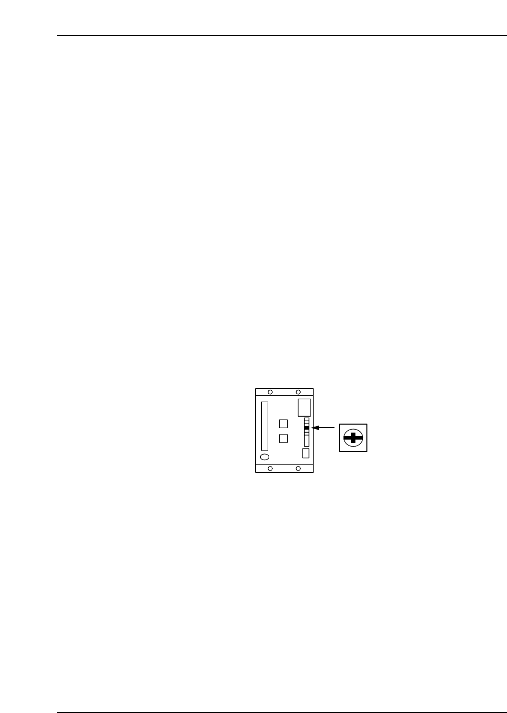
The current servo count appears on the screen. The value will fluctuate.
Turn the ZERO volume on the amp slowly to eliminate any fluctuation.
When the counter becomes stable, press CYCLE STOP.
Refer to the figure below for the location of the ZERO volume.
<C-Axis>
[V_TEST] (F3) → [ZERO] (F3) → START
The current servo count appears on the screen. The value will fluctuate.
When adjusting the amp, perform automatic zero adjustment first and then manual
adjustment.
Automatic Zero Adjustment
[MODE] (sw 4)
→ [C] [n] [-] [0] [0] will be displayed
→ [DATA] (sw 1 + sw 4)
→ [0] [0] [-] [0] [0] will be displayed
→ [▲] (sw 2)
→ [0] [0] [-] [0] [1] will be displayed
→ [MODE] (sw 4)
ZERO
CP6M5078