CP6的IO代码.pdf - 第228页
Part 5 Chapter 5 Servo Adjustments Edition 1.0 5-5-5 CP-6 Series Mechanical Reference 5.2.1 CP-642 Servo Adjustments When performing servo adjustments on the CP-642, the machine should be booted up in “Mechacheck mode”, …
Part 5 Chapter 5 Servo Adjustments
Edition 1.0 5-5-4 CP-6 Series Mechanical Reference
5.2 Servo Adjustments
The following section discusses CP-6 series servo amplifier adjustments. The two
adjustments to be discussed are:
• Zero adjustments
• Gain adjustments
Performing zero adjustments on CP-6 series amplifiers will require the use of a digital
operator.
Note: Manual zero adjustments will be necessary for analog input amplifiers, D1 and D2. For X,
Y, Z, FRQ, FQ and NC amplifiers on the CP643E and CP643ME machines, adjustments
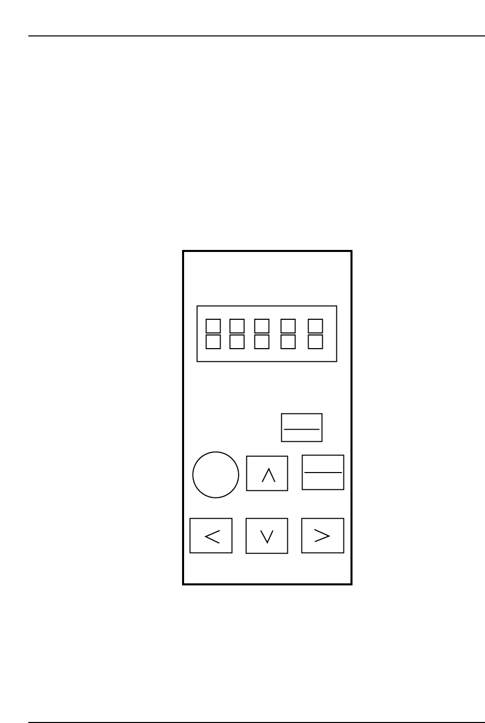
are performed on the amplifier itself. For all other amplifiers the digital operator below is
used.
RESET
Servopack
Digital
Operator
Jusp-0p02A
DSPL
SET
ALARM
JOG
SVON
DATA
ENTER
Yaskawa
Digital Operator
CP6M5077
Part 5 Chapter 5 Servo Adjustments
Edition 1.0 5-5-5 CP-6 Series Mechanical Reference
5.2.1 CP-642 Servo Adjustments
When performing servo adjustments on the CP-642, the machine should be booted up in
“Mechacheck mode”, the boot-up procedure for which is detailed in the section below.
Note: The procedure explained below is valid from ROM versions 305 or later.
Before Starting Adjustments
1) Boot-up the machine in “Mechacheck mode”.
[3] (axis change button) + RESET + POWER ON
Following this, both shutters should be raised to avoid collision with the device
tables.
2) Ensure the cam axis is at 0° and that all stopper solenoids are set to OFF.
3) Specify the axis to be adjusted:
[SERVO] (F5) → [+ PAGE], [- PAGE]
4) Prepare axis movement:
[SERVO MOVE] (F1)
5) Perform zero-setting.
Zero Adjustment
<D-Axis>
[V_TEST] (F3) → [ZERO] (F3) → START
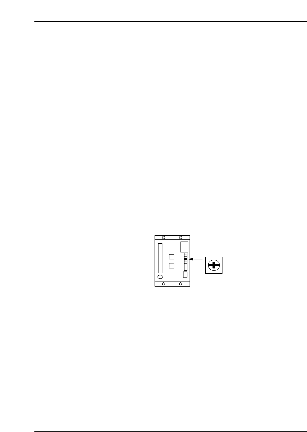
The current servo count appears on the screen. The value will fluctuate.
Turn the ZERO volume on the amp slowly to eliminate any fluctuation.
When the counter becomes stable, press CYCLE STOP.
Refer to the figure below for the location of the ZERO volume.
<C-Axis>
[V_TEST] (F3) → [ZERO] (F3) → START
The current servo count appears on the screen. The value will fluctuate.
When adjusting the amp, perform automatic zero adjustment first and then manual
adjustment.
Automatic Zero Adjustment
[MODE] (sw 4)
→ [C] [n] [-] [0] [0] will be displayed
→ [DATA] (sw 1 + sw 4)
→ [0] [0] [-] [0] [0] will be displayed
→ [▲] (sw 2)
→ [0] [0] [-] [0] [1] will be displayed
→ [MODE] (sw 4)
ZERO
CP6M5078

Part 5 Chapter 5 Servo Adjustments
Edition 1.0 5-5-6 CP-6 Series Mechanical Reference
Manual Zero Adjustment
→ [▲] (sw 2)
→ [0] [0] [-] [0] [3] will be displayed
→ Press MODE (sw 4) twice
→ [b] [_] [*] [*] [*] will be displayed
→ Press [▲] or [▼] to eliminate any fluctuation
→ Press MODE (sw 4) to register the data when the counter becomes stable
→ Press CYCLE STOP
→ [DATA] (sw 1 + sw 4)
→ [C] [n] [-] [0] [0] will be displayed
[▲]: increase the value [▼]: decrease the value
C-axis servo amp switches
[▲]: sw 2 [←]: sw 1 + sw 2 [▼]: sw 3 [→]: sw 1 + sw 3
MODE: sw 4 DATA: sw 1 + sw 4
<FQ-, FRQ-, NC-Axis>
Connect the Digital Operator to the amp.
[V_TEST] (F3) → [ZERO] (F3) → START
The current servo count appears on the screen. The value will fluctuate. When adjusting
the amp, perform automatic zero adjustment first and then manual adjustment.
Automatic Zero Adjustment
[DSPL SET]
→ [C] [n] [-] [0] [0] will be displayed
→ [DATA ENTER]
→ [0] [0] [-] [0] [0] will be displayed
→ [▲]
→ [0] [0] [-] [0] [1] will be displayed
→ [DSPL SET]
Manual Zero Adjustment
→ [▲]
→ [0] [0] [-] [0] [3] will be displayed
→ Press [DSPL SET] twice
→ [b] [_] [*] [*] [*] will be displayed
→ Press [▲] or [▼] on the Digital Operator to eliminate any fluctuation
→ Press [DSPL SET] to register the data when the counter becomes stable
→ Press CYCLE STOP to stop the axis
→ [DATA ENTER]
→ [C] [n] [-] [0] [0] will be displayed. Press [DSPL SET] to finish.
[▲]: Count value plus-side offset
[▼]: Count value minus-side offset