CP6的IO代码.pdf - 第367页
7. Advance the second board and verify that the second board check sensor switches ON when the board makes contact with the mid-stopper. 8. Check the positions of premounted parts on the lower surface of the board. Set t…
2.2 Mid-Stopper Position Alignment
When a double board production program is executed, the gap between boards is fixed
by the mid-stopper and this gap is maintained while board transport is carried out. As a
result, the mid-stopper position must be correctly set in order to accurately carry out
mark acquisition and placement.
WARNING
• Always be sure to cut off the 200V power before performing this
sensor adjustment procedure.
• The CP-643E/643ME conveyor is equipped with laser sensors.
In areas where there is a risk of eye damage from the laser beams,
be sure to install a laser beam shield at the laser emission area
before performing this sensor adjustment procedure.
1. Check the board size in the X-direction.
2. Input the following values from the operation panel.
• PCB Distance (mm)
• Pcb_X (mm)
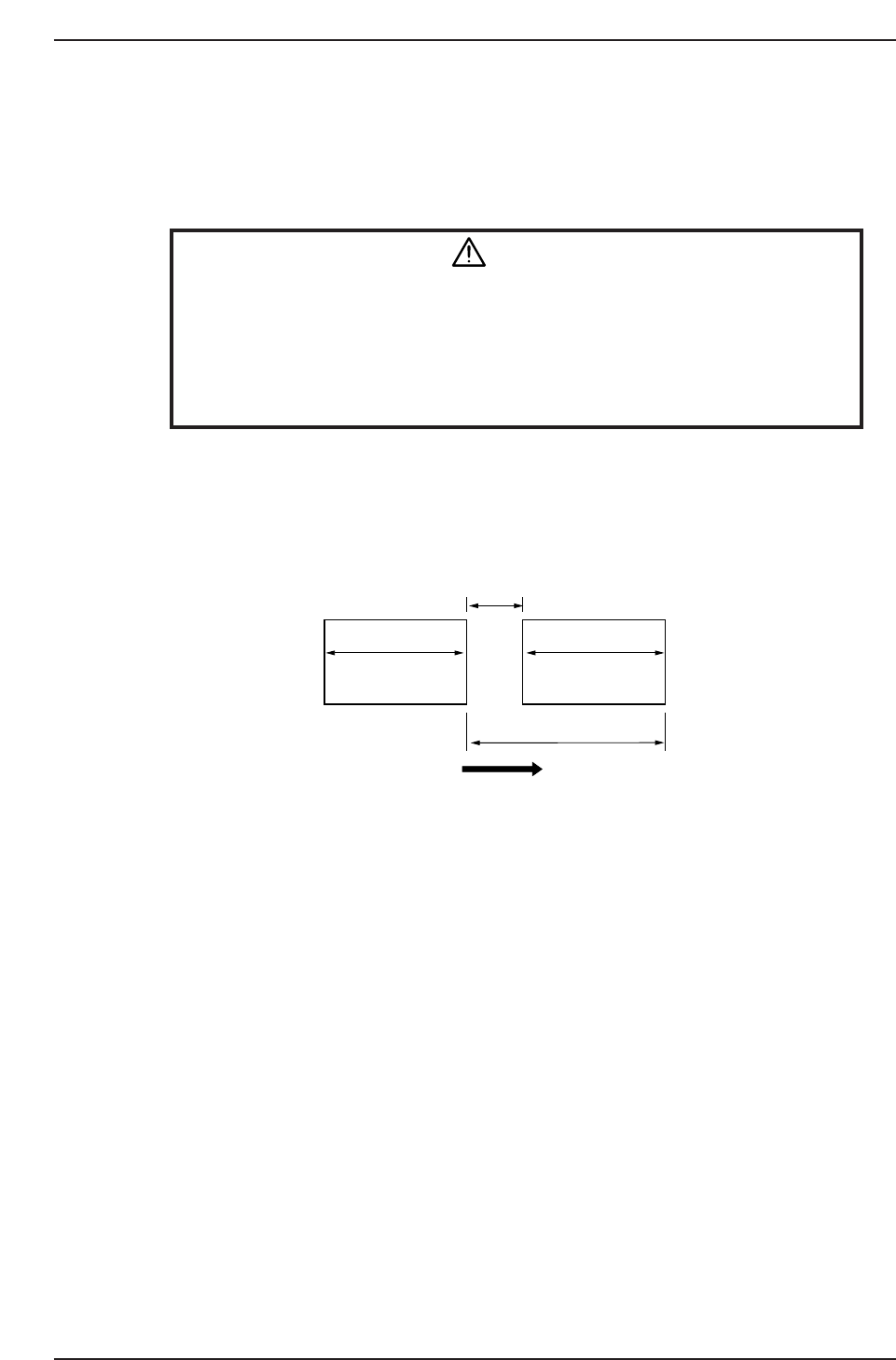
Note: A 15 mm clearance is required between the first and second boards to accommodate the
mid-stopper. At double board (tandem) production operations, the maximum dimension for
Pcb_X is 220 mm.
3. Put two boards on the in-conveyor.
4. Advance the first board forward until it makes contact with the board stopper on
the front of the in-conveyor.
5. Confirm that the first board check sensor comes ON at a position 5.0 mm from the
first board advance limit position.
6. Loosen the adjusting bolt and adjust the mid-stopper position until the first and
second board advance limits match the PCB Distance dimension which has been
specified.
CP6M10007
Board flow direction
Pcb_X Pcb_X
PCB Distance
15 mm
Second board First board
Part 10 Chapter 2 In-Conveyor
Edition 1.0 10-2-4 CP-6 Series Mechanical Reference
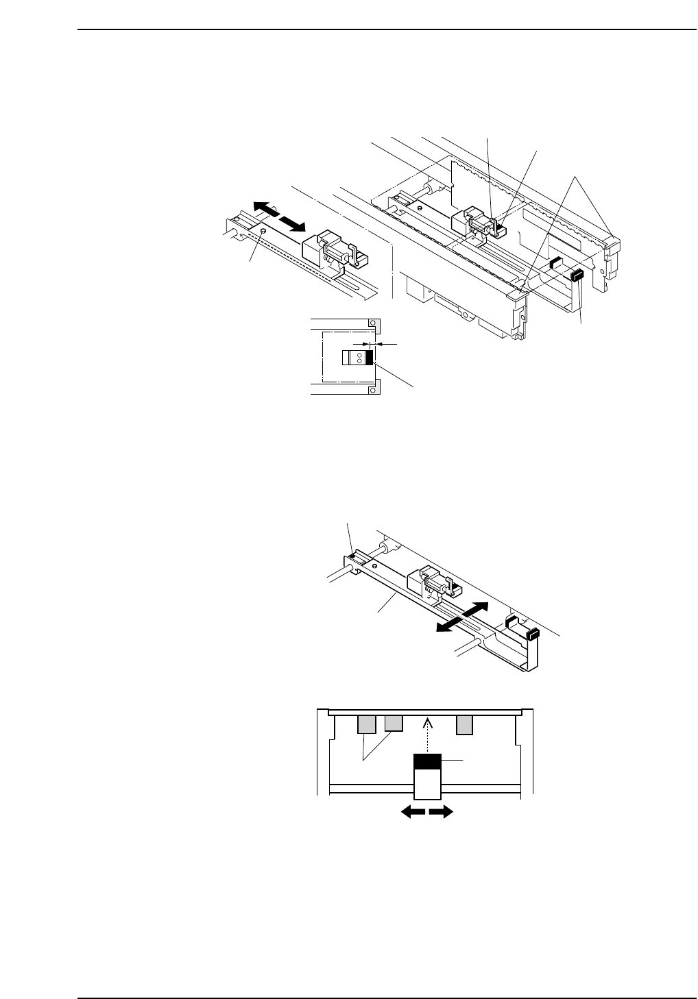
7. Advance the second board and verify that the second board check sensor switches
ON when the board makes contact with the mid-stopper.
8. Check the positions of premounted parts on the lower surface of the board.
Set the sensor avoiding the premounted part positions. Loosen the adjusting bolt
shown below and move the slider in the Y-direction to adjust the sensor position.
CP6M10009
Adjusting bolt
Slider
Y-direction
Premounted
parts
Sensor
CP6M10008
Mid-stopper
Adjustment bolt
Board stopper
5.0 mm
Second board check sensor
First board check sensor
First board check sensor
Edition 1.0 10-2-5 CP-6 Series Mechanical Reference
Part 10 Chapter 2 In-Conveyor

Notes:
Part 10 Chapter 2 In-Conveyor
Edition 1.0 10-2-6 CP-6 Series Mechanical Reference