CP6的IO代码.pdf - 第386页
Notes: Part 10 Chapter 7 Setting the Board Positioning Pins Edition 1.0 10-7-2 CP-6 Series Mechanical Reference
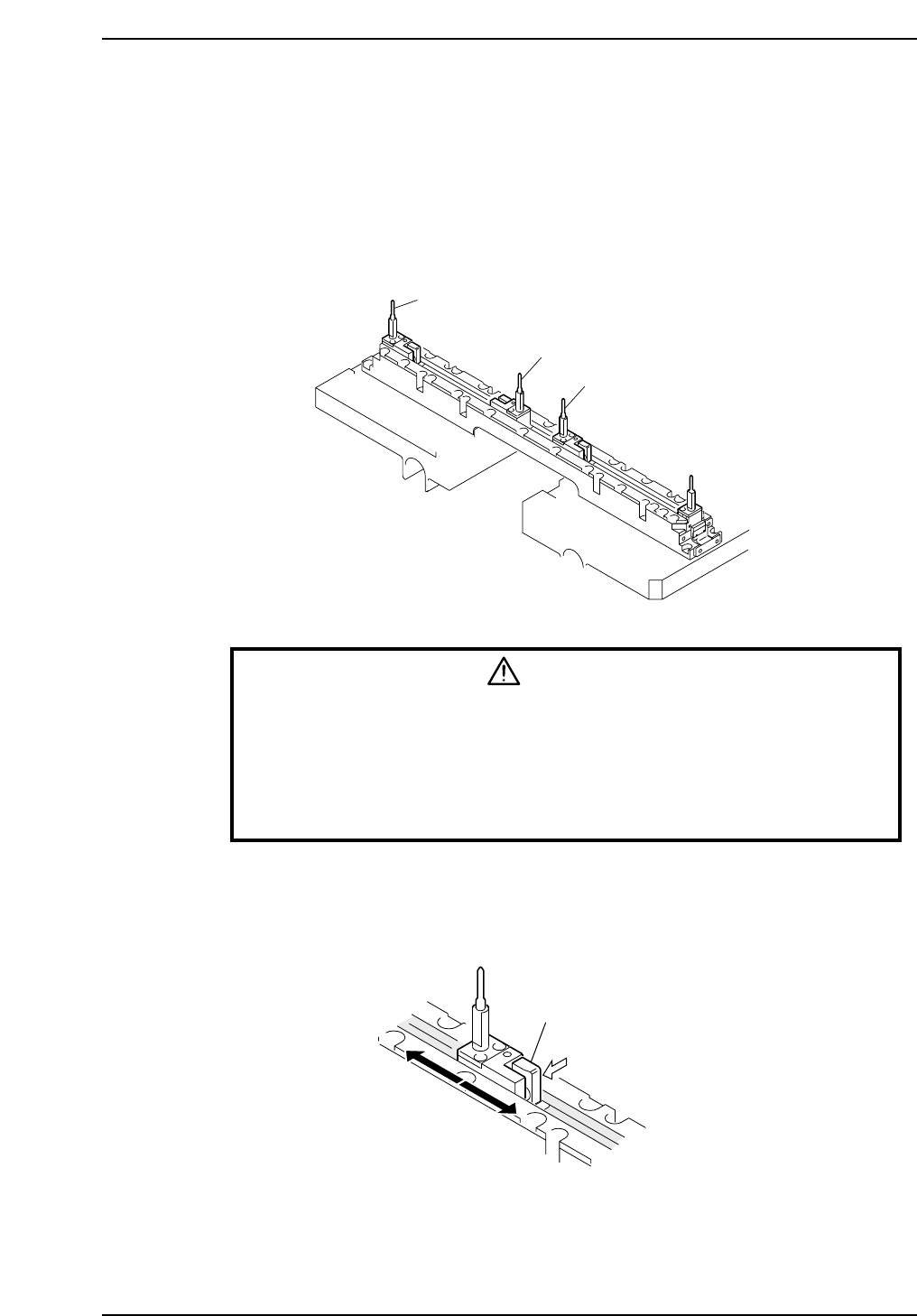
7. Setting the Board Positioning Pins
When a reference pin and follow-up pin are used, the positioning pins must be reset each
time the size of boards being transported changes.
The following pin positions must be set.
• First board follow-up pin position
• Second board reference pin position
• Second board follow-up pin position
WARNING
• Always be sure to cut off the 200V power before performing this
sensor adjustment procedure.
• The CP-643E/643ME conveyor is equipped with laser sensors.
In areas where there is a risk of eye damage from the laser beams,
be sure to install a laser beam shield at the laser emission area
before performing this sensor adjustment procedure.
Push down on the lock lever to move the pin holder and adjust the pin position to match
the board pin pitch. Also be sure to take the gap between the first and second boards
into account when setting each positioning pin.
CP6M10036
Lever
CP6M10035
First board follow-up pin
Second board reference pin
Second board follow-up pin
Part 10 Chapter 7 Setting the Board Positioning Pins
Edition 1.0 10-7-1 CP-6 Series Mechanical Reference

Notes:
Part 10 Chapter 7 Setting the Board Positioning Pins
Edition 1.0 10-7-2 CP-6 Series Mechanical Reference

Part 11
Supplementary
Information