00197195-02-UG SetupCenter 5.1_en.pdf - 第117页
Working with the Setup Center Application Splice Monitoring Splice Mo nitor User Guide SIPLACE Setup Center 5.1 11 7 Location (for feeders) ▪T h e Track , the Division and the Feeder type should come for m the SI PLACE P…
Working with the Setup Center Application
Setup Information Filter Settings
116 User Guide SIPLACE Setup Center 5.1
▪ Setup Change
▪ Set up verification data query
▪ Length of packaging chain exceeded
▪ Splice Monitor - Missing Refill
▪ Splice Monitor - Missing Splice
▪ Splice monitor: Unexpected splice
▪ Torn down outside the setup
▪ Verification history cleared
▪ Verification status uncertain
▪ Incorrectly refilled
7.3.2 Filter Settings
The data are shown with an advisable filter setting, which differs according to where the verification his-
tory is opened. These filter settings can be edited here as required.
► Enable the required filter setting and select the required data from the relevant list boxes. You may
need to enter values in the fields Packaging unit ID, Feeder ID and Table ID.
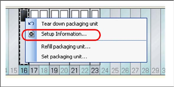
7.4 Setup Information
7.4.1 Opening Setup Information + Overview
This dialog shows the setup information from the SIPLACE Pro target setup for the selected track.
Open the context menu for a configured feeder and select the function => Setup information...
This dialog shows the setup information from the SIPLACE Pro target setup for the selected track.
Working with the Setup Center Application
Splice Monitoring Splice Monitor
User Guide SIPLACE Setup Center 5.1 117
Location (for feeders)
▪The Track, the Division and the Feeder type should come form the SIPLACE Pro target setup.
Location (for trays)
▪The Level, the Division and the Feeder type come from the SIPLACE Pro target setup.
Component
▪ The name of the Component, the Component shape and, if available, the Brightness class from the
SIPLACE Pro target setup.
Barcodes
▪ The Barcodes (supplier barcodes) and Filter come from the SIPLACE Pro target setup.
Alternative components
▪ If you have defined alternative components for this component, these will be shown here.
7.5 Splice Monitor
The splice sensor must be active. You can see the settings for the splice sensor via Extras Settings
Common Settings for Online setup verification Splice Monitoring. See "3.2.1 Settings of Online Setup
Verification" [ ➙ 27].
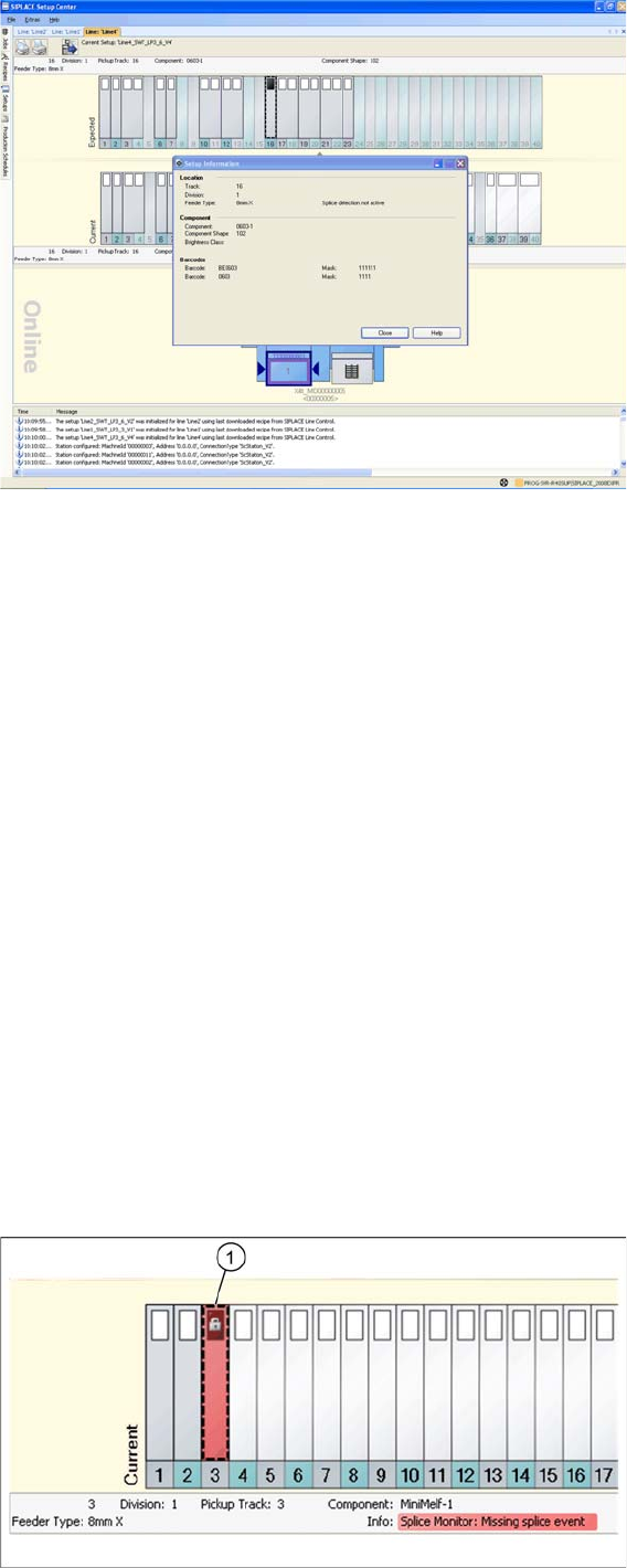
7.5.1 Splice Monitoring
If a splice point is expected for a track and the set overshoot value is reached, this track is deactivated
at the station and displayed in red with an error symbol in Setup Center (1). Detailed information will be
shown in the notifications window.
Working with the Setup Center Application
Splice Monitor Splice Monitoring
118 User Guide SIPLACE Setup Center 5.1
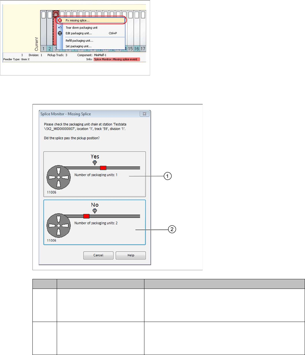
7.5.1.1 Correcting Splice Errors with the Setup Center GUI
Step-by-Step Procedure
Step 2:
Confirm the following question which appears:
Step 3:
► If the Activate pickup position with verification function has been activated, it is necessary to scan
the barcode with the barcode fragment "Component" or "UID" in order to activate the track, otherwise
the track will automatically be deactivated.
The component level on the packaging unit has now been matched with the data in Setup Center.
Step 1:
► Open the context menu with a right mouse-click and
start the Fix missing splice …function.
Icon Action Meaning
1Yes - the splice point has al-
ready passed the pickup posi-
tion.
Rejects the current packaging unit (packaging unit will no
longer be recorded), the quantity of the following packaging
unit remains the same and all information is sent to the sta-
tion.
2No - the splice point has not yet
reached the pickup point.
Sets the quantity of the current packaging unit to the thresh-
old value (for example: 1% of 1000 = 10 components), the
quantity of the following packaging unit is set to the original
quantity and all information is sent to the station.