00197195-02-UG SetupCenter 5.1_en.pdf - 第43页
Configuring Setup Center Connecting a Datalogic Scanner Docking Stations User Guide SIPLACE Setup Center 5.1 43 Functions Icons in the List of Existing Docking Stations If no icon is displaye d, there is cu rrently no in…
Configuring Setup Center
Docking Stations Connecting a Datalogic Scanner
42 User Guide SIPLACE Setup Center 5.1
Packaging unit XML import
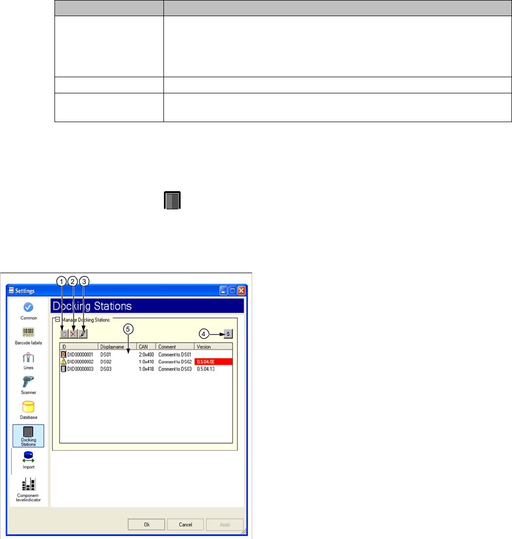
3.8 Docking Stations
► In the main menu open Extras > Settings and the Settings window is opened.
► Select the category Docking Stations and the settings are opened.
In this view the settings for the pre-setup unit of the SX and X series are made.
@ToDo/Review: Neuer Screenshot mit neuen Symbolen (bei 1,2 und 3) und Fördererkitting in der Ta-
belle
Settings Meanings
Active Activate/deactivate to import XML files with packaging unit information.
The XML files are regularly read and imported into the Setup Center database.
If packaging unit information are not imported, the reasons for this are pointed
out in the notifications window.
Polling interval (min) Time interval for importing the XML files.
Import directory Relative path of the XML files to the SIPLACE Setup Center directory. The de-
fault import folder "Import" is created during the installation.
Legend
1. Add docking station
2. Remove selected docking station
3. Edit selected docking station
4. Updating the information on a connected docking sta-
tion
5. List of existing docking stations
Configuring Setup Center
Connecting a Datalogic Scanner Docking Stations
User Guide SIPLACE Setup Center 5.1 43
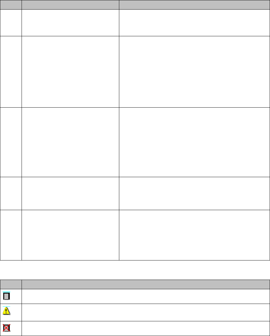
Functions
Icons in the List of Existing Docking Stations
If no icon is displayed, there is currently no information on the status of the connection and the docking
station.
Icon Designation Description
1 Add docking station Select the Add Docking Station icon.
The Docking Station dialog box will open. See "3.8.1
Docking Station Dialog Box" [ ➙ 44].
2 Remove selected docking station Mark a docking station and select the "remove selected
docking station" icon.
-Or-
Mark a docking station in the selection list and select Re-
move from the context menu.
The entry is removed irrevocably even if you quit the
configuration dialog with Cancel.
3 Edit Selected Docking Station Mark a docking station and select the Edit Selected
Docking Station icon.
-Or-
Mark a docking station in the selection list and select Edit
from the context menu.
The Docking Station dialog box with the relevant settings
will open. See "3.8.1 Docking Station Dialog Box"
[➙44].
4 Update Docking Station You can test the connection of all entered docking sta-
tions and update the version numbers. If the connection
is not established, the corresponding error messages
will be issued in the notifications window.
5 Download Firmware Open the context menu in the list of existing docking sta-
tions and the Download Firmware function will be dis-
played in addition. Select this function to update the
firmware of the selected docking station.
See "7.10.3.1 Firmware Download to the Docking Sta-
tions" [ ➙ 139].
Icon Description
The docking station was recognized and successfully connected.
The displayed software version of the docking station does not correspond to the current sta-
tus.
The docking station could not be connected.
Configuring Setup Center
Material Reorder Docking Station Dialog Box
44 User Guide SIPLACE Setup Center 5.1
3.8.1 Docking Station Dialog Box
► After you have made all settings confirm these with OK.
3.9 Material Reorder
► In the main menu open Extras > Settings and the Settings window is opened.
► Select the category Material reorder and the settings are opened.
Material Reorder
After a successful setup verification the packaging unit can be marked for reordering. This is usually the
case if the line operator has taken the last packaging unit of a part number from the Kanban storage.
The "Reorder" information is saved in the database or can be sent as a message via OIB.
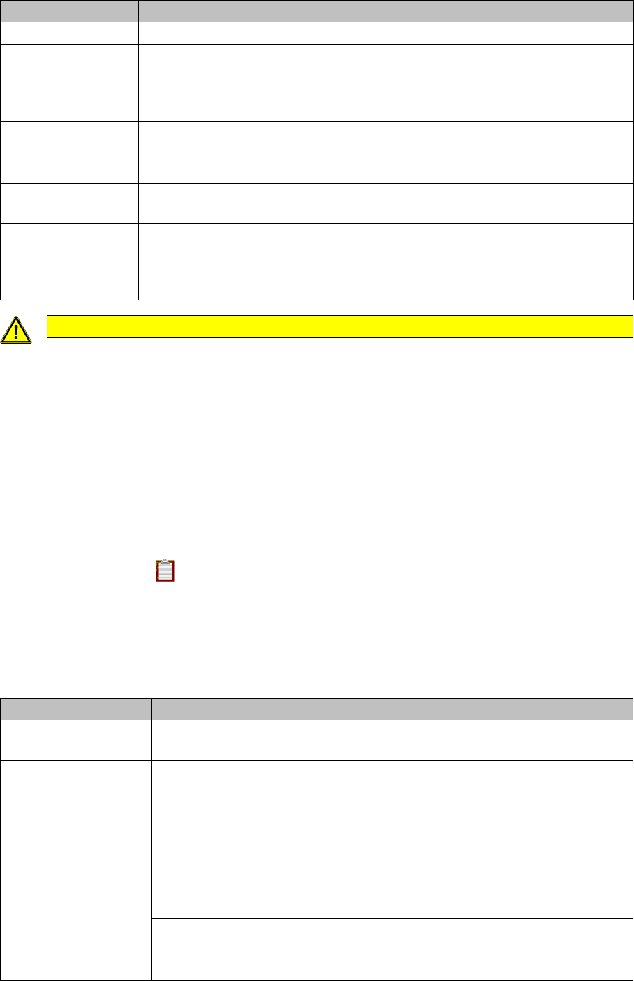
Settings Meanings
Display name Freely selectable name for the docking station. It is used for display only.
ID Text that is printed on the barcode label of the docking station. The format is:
sssnnnnnnnn
s: Three letters fro identifying the customer
n: Eight digits for identifying the docking station at the customer.
Comment A random text that gives further information on the docking station.
CAN The address of the CAN interface on the docking station. This address is set via
switches on the rear side of the docking station.
Bus The number of the CAN interface on the CAN interface board to which the dock-
ing station is connected.
Feeder kitting If a docking station is to be used as a feeder kitting station, the kitting function
can be enabled permanently. If a docking station is permanently enabled as a
feeder kitting station, you no longer need to scan in a control barcode to start the
component feeder kitting function.
CAUTION
Check the docking station settings
Please note that Setup Center cannot communicate with the docking station if these settings
are faulty. For this reason, carefully check the settings of the switches on the rear side of the
docking station and the cabling of the docking station with the CAN interface on the computer
on which the Setup Center is installed.
Settings Meanings
Reorder material dur-
ing Online-Verification
Activates reordering of packaging units after a successful online setup verifi-
cation.
Reorder material dur-
ing Offline-Verification
Activates reordering of packaging units after a successful offline setup verifi-
cation.
Reorder material via Database view
The material reorder is saved as a data set in the Setup Center database with
the parameters Component name, Line, Station, Location no, Date/time. Line,
station and location number indicate the location where the component was
refilled. The reorder data sets can be read out via the database view
v_Reorder.
Web service
The Web service settings field is activated. The material reorder is sent as a
message via OIB. See the OIB documentation for further information.