NR_WPW_WPC_F3_F4.pdf - 第23页
Nac hrüstanleitung/R etrofitting Instruc tions WPW an SIPLACE 80F3/F4 / WPC on SIP LACE 80F3/F4 Aus gabe 09/96 / 09/96 Edition Seite/ Page 11 von/ of 12 \ SP 1_Marke1_P os_x_i st \ 426500, \ SP 1_Marke1_P os_y_ist \ 4910…
WPW an SIPLACE 80 F3/F4 / WPC on SIPLACE 80 F3/F4 Nachrüstanleitung/Retrofitting Instructions
Ausgabe 09/96 / 09/96 Edition
Seite/Page 10 von/of 12
•
Boot up the Sitest using the Sitest start diskette.
•
Note the positions of the two heads and the gantry.
At present, table 2 cannot be measured using the PCB camera or Sitest. The table positions must be
measured manually using the calibration segment.
•
Using the segment removal tool, remove segment no. 7 (top segment) from the revolver head.
•
Insert the calibration segment.
•
Position the calibration segment in the bottom position.
•
Place the iron-type gauge on track 61 on table 2.
•
Disable the X and Y axes and push the gantry over the ‘iron’.
•
Disable the Z axis and manually position the main axes until the tip of the calibration segment is above
the indent of the ‘iron’.
Always check the position of the Z axis when moving the gantry.
•
Read the X and Y positions on the axis testing device and note the values.
•
Then place the ‘iron’ on track 120 on table 2 and repeat the measuring procedure.
•
When the measuring procedure is complete, switch the axes on again in the following :
⇒ ⇒
•
Insert the DOS diskette and edit .
•
Convert the measured track positions from digits into
µ
m (measured value x 2.5).
•
Enter the calculated values into Real.ma (see extract from Real.ma).
Nachrüstanleitung/Retrofitting Instructions WPW an SIPLACE 80F3/F4 / WPC on SIPLACE 80F3/F4
Ausgabe 09/96 / 09/96 Edition
Seite/Page 11 von/of 12
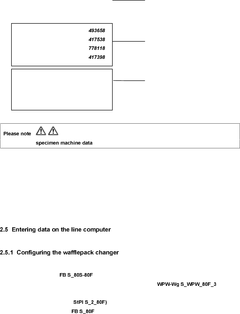
\ SP1_Marke1_Pos_x_ist \ 426500,
\ SP1_Marke1_Pos_y_ist \ 491000,
\ SP1_Marke2_Pos_x_ist \ 0,
\ SP1_Marke2_Pos_y_ist \ 0,
\ SP2_Marke1_Pos_x_ist \
,
\ SP2_Marke1_Pos_y_ist \ ,
\ SP2_Marke2_Pos_x_ist \ ,
\ SP2_Marke2_Pos_y_ist \ ,
\ SP3_Marke1_Pos_x_ist \ 778670,
\ SP3_Marke1_Pos_y_ist \ 1304473,
\ SP3_Marke2_Pos_x_ist \ 178348,
\ SP3_Marke2_Pos_y_ist \ 1304505,
This is merely . The values shown in bold and italics must be measured.
•
Save the modified machine data and remove the DOS diskette.
•
Open the Siplace 80F configuration editor.
•
Delete the component set in conveying area 1.
•
Set the desired wafflepack changer carriages in conveying area 1. for the
WPC 80F/3 wafflepack changer.
•
Configure conveying area 2 ( .
• Set the settable component in conveying area 2.
Conveying area fiducial for WPC
Fixed position, may not be changed
Conveying area fiducial 80 F
half setting range tracks 61 to 120
Conveying area fiducial 80 S
Complete setting range
WPW an SIPLACE 80 F3/F4 / WPC on SIPLACE 80 F3/F4 Nachrüstanleitung/Retrofitting Instructions
Ausgabe 09/96 / 09/96 Edition
Seite/Page 12 von/of 12
•
Save the configuration file.
•
Switch to the data manager and translate the configuration file .
•
Check the error message file
•
Start the consistency check for all setups already present.
•
Check the consistency check error message files
•
Use the UNIX line computer operating instructions in order to create the individual wafflepack
magazines for the wafflepack changer.
3RVVLEOHHUURUV
−
Wafflepack changer fiducial not found
⇒
Wafflepack changer not aligned correctly
(field of view of PCB camera).
−
Component not picked up
⇒
Wrong X or Y coordinates of wafflepack magazine
−
Pick-up position too high/low
⇒
Wrong Z position of wafflepack magazine