00900160-01_UM_ASM-ProcessLensDualLane_en.pdf - 第47页
3 Machine description 3.1 Overview of the modules Instruction Guide ASM ProcessLens Dual-lane 06/2018 47 3.1.3 PCB conveyor assembly Fig.30: PCB Conveyor A Front side of the machine B Rear side of the machine 1 Lane 1 2…
2 Safety
2.3 Safety instructions for transporting the machine
Instruction Guide ASM ProcessLens Dual-lane 06/2018 29
2.3 Safety instructions for transporting the machine
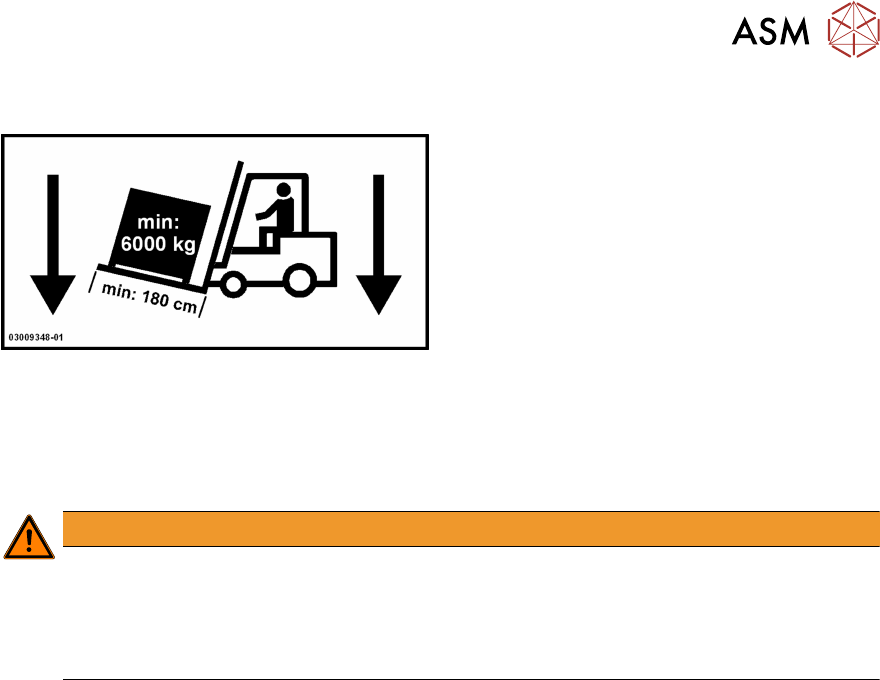
Use a forklift truck with the following specification to carry the machine:
Fork length: min. 1800 mm
Carrying power: min. 6000 kg
Clear width between forks: min. 350 mm
WARNING
Risk of tipping
If the required specification cannot be applied to the forklift, there is a risk that the forklift
will tip over when carrying the machine.
Transportation of the machine is described in section 4.1 "Transport and delivery configura-
tion" [}55].
3 Machine description
3.1 Overview of the modules
Instruction Guide ASM ProcessLens Dual-lane 06/2018 47
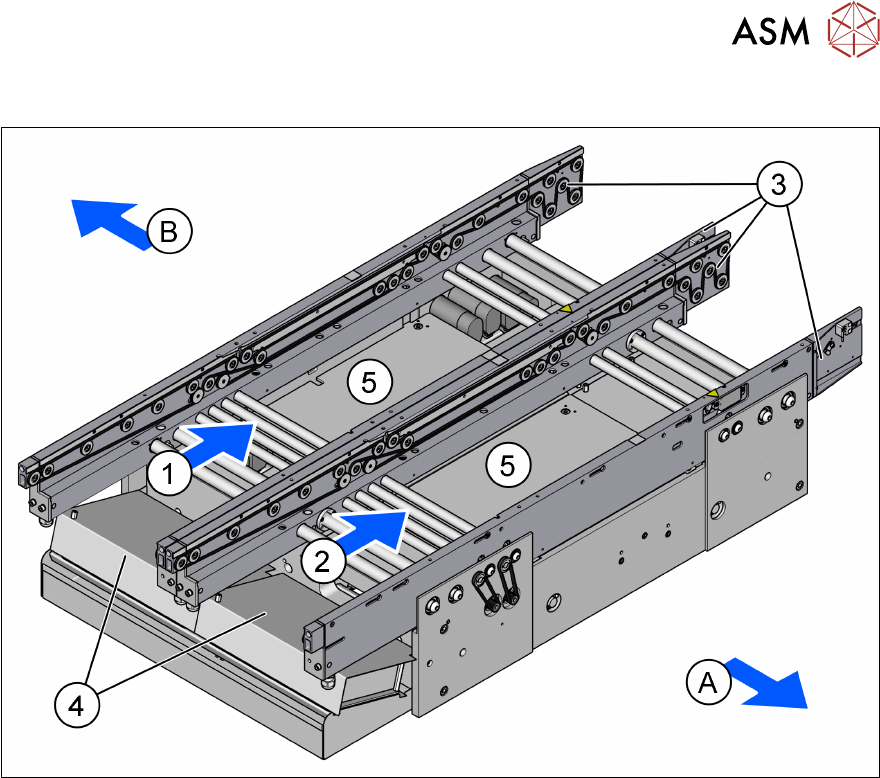
3.1.3 PCB conveyor assembly
Fig.30: PCB Conveyor
A Front side of the machine B Rear side of the machine
1 Lane 1 2 Lane 2
3 Conveyor rails 4 Conveyor control units
5 Lifting tables
3.1.3.1 Description
The PCB conveyors are designed as three-part conveyors with input, processing and output con-
veyor sections. The two areas, input conveyor and output conveyor, serve as buffer zones for the
printed circuit boards.
The conveyor belts are driven by brushless DC motors. Light barriers monitor and control transport-
ation of the boards. Once the board has reached the placement area and has passed the light bar-
riers, it is braked. A laser light barrier records the position of the board. As soon as the circuit board
has reached its target position, the conveyor belt is stopped and the board is clamped from below.
The width of the circuit board conveyor is set and monitored by an integral control circuit. It can be
selected by calling up the program. The control electronics activate the drive motor until the re-
quired width has been reached. The width adjustment is therefore independent of other machine
components.
The conveyor height can be selected on the machine to allow the machines to be integrated into
lines with a conveyor height of, 900, 930 or 950 mm. The standard height is 930 mm.
The communication between the PCB conveyors of the individual machines takes places via the
SMEMA interface.
2 Safety
2.5 Safety features
34 Instruction Guide ASM ProcessLens Dual-lane 06/2018
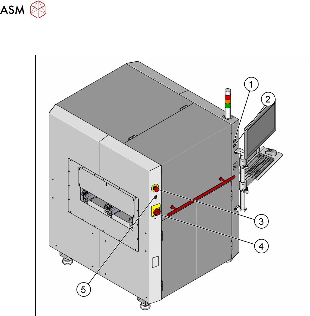
2.5.2 Switches and buttons on the machine
2.5.2.1 Position of switches and buttons on the machine
Fig.26: Position of buttons and switches
1 Start button (green) 2 Stop button (black)
3 EMERGENCY STOP button 4 Main switch
5 Key switch