00900160-01_UM_ASM-ProcessLensDualLane_en.pdf - 第49页
3 Machine description 3.1 Overview of the modules Instruction Guide ASM ProcessLens Dual-lane 06/2018 49 1 Front board edge 2 Max. 2.5 mm 3 Conveyor rail 4 PCB transport direction 5 Max. 2.5 mm 6 Max. 3 mm 3.1.4.2 Maximu…
2 Safety
2.5 Safety features
34 Instruction Guide ASM ProcessLens Dual-lane 06/2018
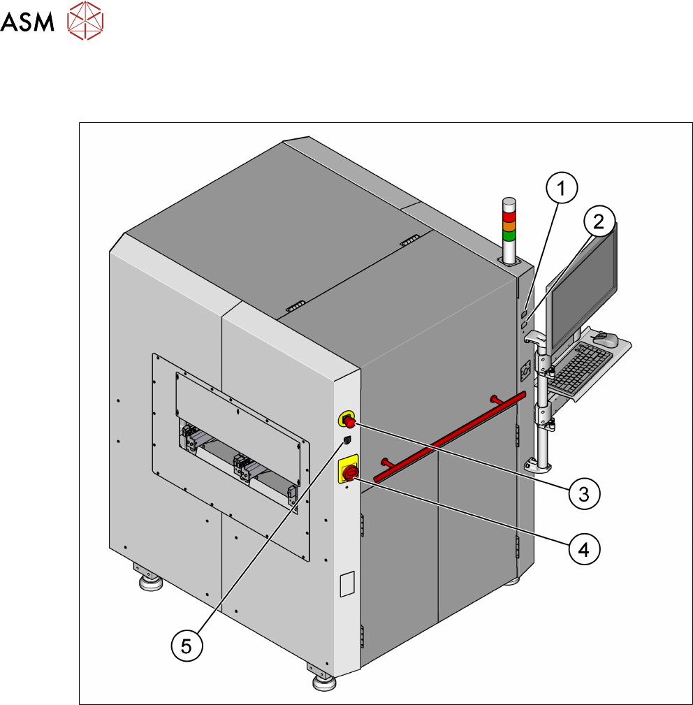
2.5.2 Switches and buttons on the machine
2.5.2.1 Position of switches and buttons on the machine
Fig.26: Position of buttons and switches
1 Start button (green) 2 Stop button (black)
3 EMERGENCY STOP button 4 Main switch
5 Key switch
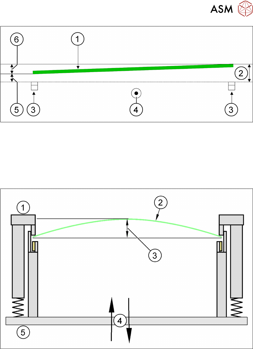
3 Machine description
3.1 Overview of the modules
Instruction Guide ASM ProcessLens Dual-lane 06/2018 49
1 Front board edge 2 Max. 2.5 mm
3 Conveyor rail 4 PCB transport direction
5 Max. 2.5 mm 6 Max. 3 mm
3.1.4.2 Maximum PCB warpage allowed during processing of the board
There is active PCB warpage measurement and tracking during the inspection so that images re-
main in sharp focus, ensuring best height measurement accuracy on the market.
1 Fixed clamped edge 2 Printed circuit board
3 ≤ 2 mm 4 Movable clamping device
5 Conveyor rail
PCB warpage down, max. 4.5 mm
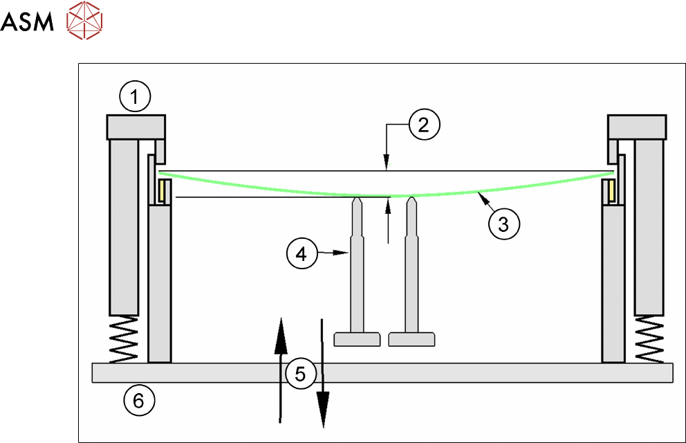
3 Machine description
3.1 Overview of the modules
50 Instruction Guide ASM ProcessLens Dual-lane 06/2018
1 Fixed clamped edge 2 0.5 mm
3 Printed circuit board 4 Magnetic pin support
5 Movable clamping device 6 Conveyor rail
► Use magnetic pin supports to achieve this value.