00195427-02_AI_HeadReconfigKitsD1D2_DE+EN.pdf - 第63页
Assembly instructions Head Re configuration SIPLACE D 1 / D2 Edition 03/2007 61 Flip-Chip Camera: The assembly and connection of the FC ca mera is done in the same manne r . See also "Assembly instructions: Flip-chi…
Assembly instructions Head Reconfiguration SIPLACE D1 / D2
Edition 03/2007
60
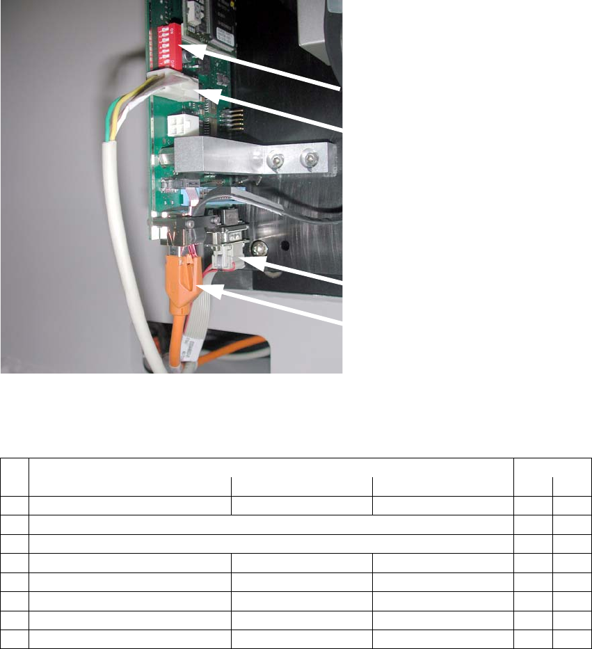
: Connect the cable to the camera:
– CAN-Bus cable X10au (03050162-)
– Hotlink cable (camera bus) X3au (03042343-)
– Power supply X4au (03040347-)
DIP switch
Power supply
X4au (03040347-)
CAN-Bus cable
X10au (03050162-)
Hotlink cable
(camera bus)
X3au (03042343-)
2
Fig. 2.7.4 Connect 3 cables to IC camera
DIP switch configuration:
2
DIP switch Gantry
No. Function ON OFF 1
1 Bootstrap —
2Reset Off
3 Gantry ID 0 Off
4 Gantry ID 1 — Off
5 Code 1 Off
6 CAN terminator with without Off
7 CAN speed = 1 Mbit/s = 500 kbit/s On
8 Camera type IC camera FC camera On
Assembly instructions Head Reconfiguration SIPLACE D1 / D2
Edition 03/2007
61
Flip-Chip Camera:
The assembly and connection of the FC camera is done in the same manner.
See also "Assembly instructions: Flip-chip camera digi
tal 16x16 (SST 25)" (00194554-). 2
2
: Fit the bottom cover with the openings on the camera base and then move it against the rear
panel.
: Use the machine spirit level to check that the camera is aligned horizontally.
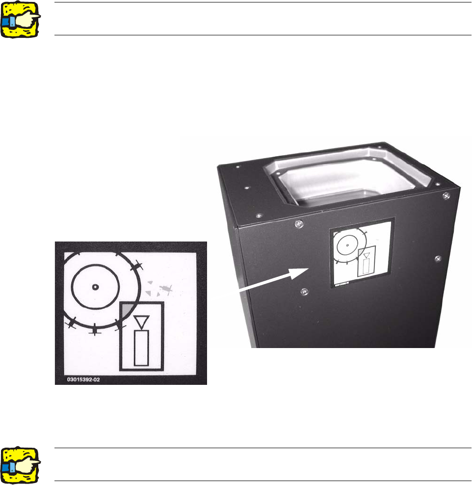
: Attach the risk of head crash warning label to the body of the camera (if it is not already at-
tached) as shown below.
2
: Carefully position the lighting unit from above (above the bottom cover) on the camera base
and fix it place with 4 screws (M4x10).
2
2The top edge of the camera should be located about 5 mm below the top edge of the PCB
conveyor. 2
Assembly instructions Head Reconfiguration SIPLACE D1 / D2
Edition 03/2007
62
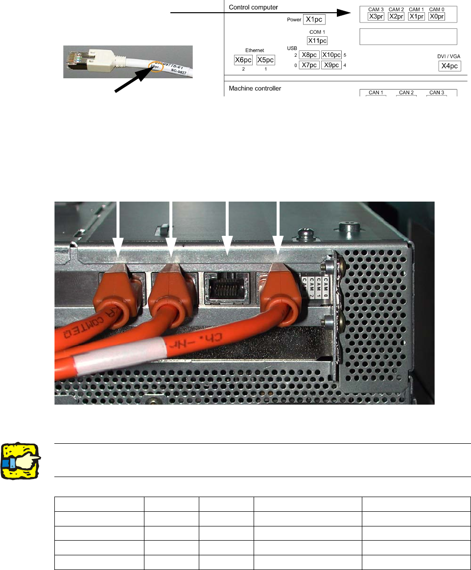
2.7.4 Hotlink card connections (Computer unit)
Hotlink cable labeling
Hotlink card for
cameras in PA 1
FC camera
X3pr
IC camera
X2pr
PCB/components
camera
Gantry 2, X1pr
PCB/components
camera
Gantry 1, X0pr
2
Fig. 2.7.5 For P&P module X0pr / X2pr
2
2Hotlink cables that are not being used must not be plugged in !!!
Do not confuse hotlink cables with twisted pair cables !!! 2
X3pr X2pr X1pr X0pr
D1
FC camera IC camera --- PCB-/Comp camera, P 1
D1 S (C&P head
--- --- --- PCB-/Comp camera, P 1
D1 S (P&P module)
FC camera IC camera --- X
D2
--- --- PCB-/Comp camera, P 2 PCB-/Comp camera, P 1